
Page 933 - 2006 HARLEY FLSTCI SERVICE MANUAL
P. 933
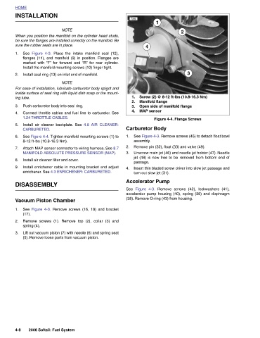
Screw (2) @ 8-12 ft-lbs (10.8-16.3 Nm)  Open side of manifold flange  Figure 4-4. Flange Screws  Remove pin (32), float (33) and valve (49).  accelerator pump housing (40), spring (39) and diaphragm


                                         3                                                     Remove screws (42), lockwashers (41),
                      2                                               See Figure 4-3. Remove screws (45) to detach float bowl Unscrew main jet (46) and needle jet holder (47). Needle jet (48) is now free to be removed from bottom end of Insert thin bladed screw driver into slow jet passage and


                 1                                    Manifold flange                                (38). Remove O-ring (43) from housing.

                             4                             MAP sensor  Carburetor Body  assembly.  passage.  turn out slow jet (31).   Accelerator Pump  Figure 4-3.


               7380                                 1.  2.  3.  4.    1.   2.  3.    4.        See


                                Place the intake manifold seal (12),  4.8 AIR CLEANER:


                     NOTE When you position the manifold on the cylinder head studs, be sure the flanges are installed correctly on the manifold. Be  flanges (11), and manifold (9) in position. Flanges are marked with  “F” for forward and  “R” for rear cylinder. Install the manifold mounting screws (10) finger tight.  Install seal ring (13) on inlet end of manifold.  NOTE For ease of installation, lubricate carburetor body spigot and inside surface of seal ring with liquid dish soap or tire mount-  Push carburetor body into seal ring. Connect throttle cables and fuel line to carburetor. See  Install air cleaner backplate. See  See Figure 4-4. Tighten manifold mountin


              INSTALLATION  sure the rubber seals are in place.  Figure 4-3.   1.24 THROTTLE CABLES.  CARBURETED.  8-12 ft-lbs (10.8-16.3 Nm).   Install air cleaner filter and cover.  DISASSEMBLY  Vacuum Piston Chamber  spring (4).  2006 Softail: Fuel System


          HOME                  See   1.  2.        ing lube.  3.  4.  5.  6.  7.  8.  9.                1.  (17).  2.  3.                                       4-8