
Page 940 - 2006 HARLEY FLSTCI SERVICE MANUAL
P. 940
4.6 4 4-15
1 2 3
7 6 5 Figure 4-10. Fuel Supply Valve Assembly See 1.27 FUEL SUPPLY VALVE FILTER: CARBURETED. Refer to Table 4-10. For diaphragm replacement and vacuum SOLUTION Connect hose to vacuum nipple. Replace valve assembly. Replace vacuum hose assembly. Replace valve assembly. Replace valve assembly. Replace valve assembly. 2006 Softail: Fuel System
9
Table 4-10. Troubleshooting Fuel Supply Valve
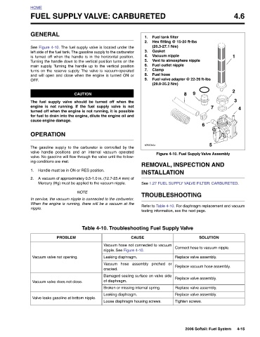
Fuel tank filter Hex fitting @ 15-20 ft-lbs (20.3-27.1 Nm) Gasket Vacuum nipple Vent to atmosphere nipple Fuel outlet nipple Clamp Fuel hose Fuel valve adapter @ 22-26 ft-lbs (29.8-35.2 Nm) 8 REMOVAL, INSPECTION AND INSTALLATION TROUBLESHOOTING testing information, see the next page. Tighten screws.
Y VALVE: CARBURETED
1. 2. 3. 4. 5. 6. 7. 8. 9. s0540x4x
CAUSE Vacuum hose not connected to vacuum nipple. See Figure 4-10. Leaking diaphragm. Vacuum hose assembly pinched or cracked. Damaged sealing surface on valve side of diaphragm. Broken or missing internal spring. Leaking diaphragm. Loose diaphragm housing screws.
Turning the handle down to the vertical position turns on the
main supply. Turning the handle up to the vertical position
and will open and close when the engine is turned ON or
turns on the reserve supply. The valve is vacuum-operated
See Figure 4-10. The fuel supply valve is located under the
left side of the fuel tank. The gasoline supply to the carburetor
is turned off when the handle is in the horizontal position.
CAUTION The fuel supply valve should be turned off when the engine is not running. If the fuel supply valve is not turned off when the engine is not running, it is possible for fuel to drain into the engine, dilute the engine oil and The gasoline supply to the carburetor is controlled by the valve handle positions and an internal vacuum operated valve. No gasoline will flow through the valve until the follow- Handle must be in ON or RES position. A vacuum of approximately 0.5-1.0 in. (12.7-25.4 mm) of Mercury (Hg) must be applied to the vacuum nipple. NOTE In service, the vacuum nipple is connected to the carbu
FUEL SUPPL cause engine damage. OPERATION ing conditions are met: PROBLEM Vacuum valve not opening. Vacuum valve does not close. Valve leaks gasoline at bottom nipple.
HOME GENERAL OFF . 1. 2. nipple.
7