Page 262 - METRO CENTER PDF BINDER 1_Neat
P. 262

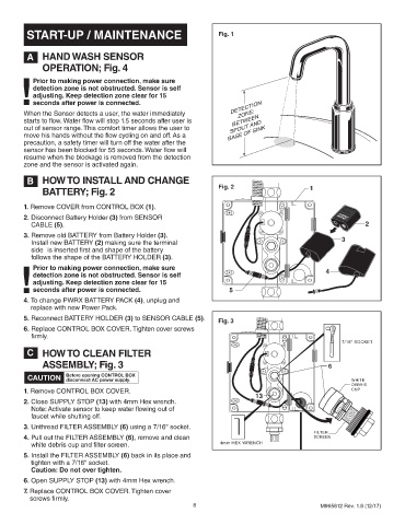
START-UP / MAINTENANCE                                    Fig. 1


         A    HAND WASH SENSOR

              OPERATION; Fig. 4

       !     Prior to making power connection, make sure
           detection zone is not obstructed. Sensor is self
           adjusting. Keep detection zone clear for 15
           seconds after power is connected.
                                                                         ZONE:
        When the Sensor detects a user, the water immediately          DETECTION
        starts to flow. Water flow will stop 1.5 seconds after user is    BETWEEN
        out of sensor range. This comfort timer allows the user to     SPOUT AND
        move his hands without the flow cycling on and off. As a      BASE OF SINK
        precaution, a safety timer will turn off the water after the
        sensor has been blocked for 55 seconds. Water flow will
        resume when the blockage is removed from the detection
        zone and the sensor is activated again.

         B    HOW TO INSTALL AND CHANGE
                                                                   Fig. 2                      1
              BATTERY; Fig. 2
        1.  Remove COVER from CONTROL BOX (1).
                                                                                                           CR-P2
        2.  Disconnect Battery Holder (3) from SENSOR
          CABLE (5).                                                                                           2
        3.  Remove old BATTERY from Battery Holder (3).
          Install new BATTERY (2) making sure the terminal                                         6    3
          side   is inserted first and shape of the battery
          follows the shape of the BATTERY HOLDER (3).
            Prior to making power connection, make sure
       !   detection zone is not obstructed. Sensor is  self                                        4
           adjusting. Keep detection zone clear for 15
           seconds after power is connected.
        4.  To change PWRX BATTERY PACK (4), unplug and               5
          replace with new Power Pack.
        5.  Reconnect BATTERY HOLDER (3) to SENSOR CABLE (5).
                                                                   Fig. 3
        6.  Replace CONTROL BOX COVER. Tighten cover screws
          firmly.
                                                                                                        7/16" SOCKET
         C    HOW TO CLEAN FILTER

              ASSEMBLY; Fig. 3                                                                      6

         CAUTION     Before opening CONTROL BOX                                                            WHITE
                     disconnect AC power supply.
                                                                                                           DEBRIS
        1.  Remove CONTROL BOX COVER.                                                                      CUP
                                                                              13
        2.  Close SUPPLY STOP (13) with 4mm Hex wrench.
                                                                                                       ttttttttttttttttttt
                                                                                                        ttttttttttttttttttt
                                                                                                        ttttttttttttttttttt
                                                                                                        ttttttttttttttttttt
                                                                                                         ttttttttttttttttttt
          Note: Activate sensor to keep water flowing out of                                           ttttttttttttttttttt ttttttttttttttttttt
                                                                                                          ttttttttttttttttttt
                                                                                                         ttttttttttttttttttt
                                                                                                          ttttttttttttttttttt
                                                                                                          ttttttttttttttttttt
                                                                                                          ttttttttttttttttttt
          faucet while shutting off.                                                                     ttttttttttttttttttt ttttttttttttttttttt
        3.  Unthread FILTER ASSEMBLY (6) using a 7/16" socket.
                                                                                                FILTER
        4.  Pull out the FILTER ASSEMBLY (6), remove and clean                                  SCREEN
          white debris cup and filter screen.                       4mm HEX WRENCH
        5.  Install the FILTER ASSEMBLY (6) back in its place and
          tighten with a 7/16" socket.
          Caution: Do not over tighten.
        6.  Open SUPPLY STOP (13) with 4mm Hex wrench.
        7.  Replace CONTROL BOX COVER. Tighten cover
          screws firmly.
                                                           8                                        M965612 Rev. 1.8 (12/17)
   257   258   259   260   261   262   263   264   265   266   267