
Page 422 - Installation Training Binder FIT1-3
P. 422
2. Assemble the wall components by matching the labeled part numbers
shown on the CAD drawing. For the required configuration, use the slots
on the adjustable components for proper sizing.
3. Using containment wall components as a template mark the location of the
holes to be drilled in the floor.
4. Remove the containment walls carefully and note the orientation of the
components.
I. Assembling Barrier Walls
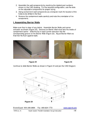
Make sure floor is clear of any debris. Assemble Barrier Walls and corner
extrusion as shown (Figure 22). Grooves on Barrier Wall must face the inside of
containment barrier. Slide the lip on each corner extrusion into the
corresponding groove on the Barrier Wall (Figure 23). Adjust Barrier Walls so
that liner fits flush against walls.
Figure 22 Figure 23
Continue to slide Barrier Walls as shown in Figure 24 and per the CAD Diagram.
Figure 24
EnviroGuard 800-206-9884 Fax 909-624-1772 www.egsintl.com
10/08 rev. A Hawk System Retrofit Installation Setup Instruction - 9 -