
Page 14 - Handout of Computer Architecture (1)..
P. 14
The processor chip shown in Figure 1.2 does not represent any specific product, but provides a
general idea of how such chips are laid out. Next, we zoom in on the structure of a single core,
which occupies a portion of the processor chip. In general terms, the functional elements of a
core are:
■ Instruction logic: This includes the tasks involved in fetching instructions, and decoding each
instruction to determine the instruction operation and the memory locations of any operands.
■ Arithmetic and logic unit (ALU): Performs the operation specified by an instruction.
■ Load/store logic: Manages the transfer of data to and from main memory via cache.
The core also contains an L1 cache, split between an instruction cache (I- cache) that is used for
the transfer of instructions to and from main memory, and an L1 data cache, for the transfer of
operands and results.
Typically, today’s processor chips also include an L2 cache as part of the core. In many cases, this
cache is also split between instruction and data caches, although a combined, single L2 cache is
also used. Keep in mind that this representation of the layout of the core is only intended to give
a general idea of internal core structure.
In a given product, the functional elements may not be laid out as the three distinct elements
shown in Figure 1.2, especially if some or all of these functions are implemented as part of a
microprogrammed control unit. examples It will be instructive to look at some real- world
examples that illustrate the hierarchical structure of computers.
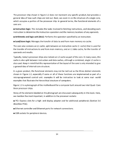
Figure 1.3 is a photograph of the motherboard for a computer built around two Intel Quad- Core
Xeon processor chips.
Many of the elements labeled on the photograph are discussed subsequently in this book. Here,
we mention the most important, in addition to the processor sockets:
■ PCI- Express slots for a high- end display adapter and for additional peripherals (Section 3.6
describes PCIe).
■ Ethernet controller and Ethernet ports for network connections.
■ USB sockets for peripheral devices.
14