
Page 25 - SAPEM-Chapter-10-2nd-edition-2014
P. 25
South African Pavement Engineering Manual
Chapter 10: Pavement Design
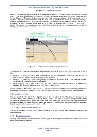
reduced. The deflection bowl is represented by the white line, and the blue arrows indicate the locations of the FWD
sensors. The sensor immediately underneath the FWD load measures the largest deflection. All the layers contribute
to that deflection. The sensor furthest away from the load measures a deflection that is generated from the
subgrade. The closer the sensor to the load, the more layers contribute to the deflection. The deflection bowl,
therefore, provides information about the individual layers, by investigating the shape of the bowl. For example,
deflection bowl from a pavement with a weak base layer shows an increased deflection at the first three sensors.
Section 7.5 presents some guidelines for using deflections to analyse and characterise pavements, and also to
identify problem layers in the pavement.
Figure 8. Stress Distribution Versus Deflections
The influence of the pavement structure on the deflection bowls is illustrated by three different scenarios shown in
Figure 9:
• Scenario 1 is a stiff pavement, with a relatively stiff and strong cemented subbase layer. The deflection is
relatively low, and the bowl wide in comparison to its magnitude.
• Scenario 2 is a pavement that is relatively old, but has good quality materials. The deflection is higher
than Scenario 1, because the pavement is less stiff.
• Scenario 3 is an old pavement with that has poor quality materials, and has a moist subbase and
subgrade. The deflection is large, and the width of the bowl is narrow.
Section 7.5 later in this chapter, and Chapter 2: 2 contain discussion on the behaviour of various pavement layer
types under vehicle loading. Chapter 6: 7.3.4.1 contains more on deflection measurements and backcalculation.
3.5.2 Load Sensitivity
The load sensitivity of a pavement is typically used in the conversion of the traffic axle load spectrum to an
equivalent design traffic estimate in terms of standard axles. The type of pavement and pavement balance
determine the load sensitivity of a particular design. Hence, the same traffic load spectrum may convert to different
equivalent standard axle values, depending on the load sensitivity. Load sensitivity and the conversion of actual axle
loads to standard axles are discussed in Section 4.1.3.
3.5.3 Long-Term Pavement Behaviour
The typical long term behaviour under loading of flexible, rigid and concrete block pavements is different, as
described below.
3.5.3.1 Flexible Pavements
The long term behaviour and distress of the different types of flexible pavement share some general phases and
trends, as illustrated in Figure 10.
Section 3: Design Considerations
Page 14