
Page 33 - UL_Report On_Part 1
P. 33
25 IITGN-UL/Façade 26 IITGN-UL/Façade
f. Fire fighting Single swing steel stiffened doors of 16 gauge galvanized steel incorporating Curtain wall Insulation: 2B 2G
single point latches are installed. Thickness of door is 46mm (1-3/4”). Steel 2D
The test facility is provided with an external hydrant system. stiffened doors are known for their rigidity and are available in varying a. Forming material 2I
Underground mains are laid 1m below the ground level. Hydrant stand strength and quality. Spacing between stiffeners is about 4” and are welded to
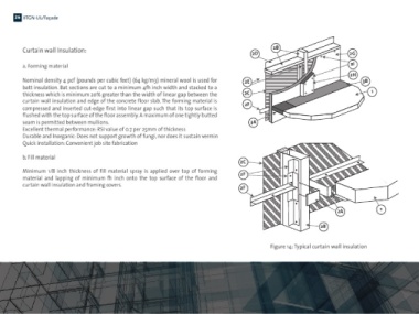
post (single) with nominal pipe size 75mm made of mild steel and each other at the top and bottom and to the inside door skin. The cavities are Nominal density 4 pcf (pounds per cubic feet) (64 kg/m3) mineral wool is used for 2E 2H 3B
having 80mm flanged inlet and outlet (ANSI B 16.5 150# or other), filled with special core. In the test, cavities in the doors used are filled with batt insulation. Bat sections are cut to a minimum 4½ inch width and stacked to a
mouthed with standard 63mm size hydrant valve is installed at a mineral Rockwool (4-pcf). thickness which is minimum 20% greater than the width of linear gap between the 2C 1
distance of 3m from the face of the building. Door leafs are provided with vision panels for visibility. These doors are curtain wall insulation and edge of the concrete floor slab. The forming material is
Fire brigade inlet having gunmetal body with three gunmetal male provided with glass panels of size 100 sq. in. compressed and inserted cut-edge first into linear gap such that its top surface is 2F
instantaneous inlets of size 63mm (with NRV) and 100mm size flanged flushed with the top surface of the floor assembly. A maximum of one tightly butted
outlet are connected to dry riser piping. Fire brigade inlet body is h. Fire stop seam is permitted between mullions. 3A
provided with drain valve. Excellent thermal performance: RSI value of 0.7 per 25mm of thickness
Internal hydrants are provided inside the building near the exit staircase A gap is always provided between the cladding and the deck slab of the Durable and Inorganic: Does not support growth of fungi, nor does it sustain vermin
area at each floor. One hose reel arrangement is provided at every building to avoid crashing of glass in case of unwanted vibrations and also to Quick installation: Convenient job site fabrication
internal hydrant location. mitigate effects of thermal expansion. This gap is about 150mm and in each
Galvanized iron pipes conforming to IS: 1239 are used for hydrant system. test needs to be filled with a suitable fire stop material. In case of fire event, the b. Fill material
Pipes were painted with a coat of primer and two coats of synthetic performance of the façade as well as of the fire stop material is crucial for the 2C
enamel paint are applied for above ground piping whereas for overall performance of the building. Fire stop material should have sufficient Minimum 1/8 inch thickness of fill material spray is applied over top of forming
underground piping coating and wrapping are done as per IS standards. fire rating to prevent fire from spreading internally. material and lapping of minimum ½ inch onto the top surface of the floor and 2F
Tests 1, 2 and 3 utilizes UL rated glasswool as fire stop material whereas test 4 curtain wall insulation and framing covers.
g. Fire doors utilizes normal fire stop material provided in form of plywood sheets which 2F
results in internal fire spread due to premature failure of fire stop material
1.5 hour UL rated fire doors are used between the compartments to before glass breakage. 1.5 hour rated fire stop material is used at each floor level
prevent propagation of fire and smoke from one compartment to for tests 1, 2 and 3. 2A 1
another at same level during a test.
2B
Figure 14: Typical curtain wall insulation