Page 38 - UL_Report On_Part 1
P. 38

29 IITGN-UL/Façade                                                                                                                                                           30 IITGN-UL/Façade


                                                                                                                                                                                                                                                                              21 # R 6 4                                         21 # R 6 5

                                                                                                                                                                                                                                                                                          21 # R 6 8
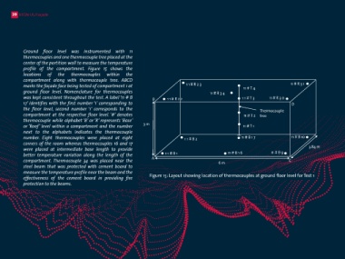
             Ground floor level was instrumented with 11                                                                                                                              Figure 16 and Figure 17 show  the locations of  the                   B                                                            21 # R 5
             thermocouples and one thermocouple tree placed at the                                                                                                                    thermocouples at first and second floor levels. Four                              21 # T R4                                 21 # T L4         D
             center of the partition wall to measure the temperature                                                                                                                  thermocouples were placed at four roof corners of the                                                  Thermocouple
                                                                                                                                                                                                                                                                                             tree
             profile of  the compartment. Figure 15 shows  the                                                                                                                        compartment, whereas  TC 68 was placed near  the                                                                            21 # T L3
             locations   of   the    thermocouples    within    the                                                                                                                   beam beneath  the cement board at first floor level.                             21 # T R3
             compartment along with  thermocouple  tree. ABCD                                                                                                                         Two thermocouple trees were placed at two ends of
             marks the façade face being tested of compartment 1 at                           1 1 # R 2 3                  11 # T 4                11 # R 3 1                         the façade face being tested. Second floor comprises of                 3 m      21 # T R2                                  21 # T L2
             ground floor level. Nomenclature for  thermocouples                                          11 # R 3 4                                                                  four  thermocouples at four roof corners without
             was kept consistent throughout the test. A label ‘11 # B        B       1 1 # R 2 2                          1 1 # T 3     11 # R 3 0                                    thermocouple  trees being placed at  this level.                                 21 # T R1                                  21 # T L1
             17’ identifies with the first number ‘1’ corresponding to                                                                             D                                  Thermocouples were not provided at base on first and                                                                                                3.84 m
             the floor level, second number ‘1’ corresponds  to  the                                                               Thermocouple                                       second floor due to less temperature change occurring                 A                                                                      C
             compartment at  the respective floor level. ‘#’ denotes                                                       11 # T 2  tree                                             through composite deck slab and effective fire stop                                                       6 m
             thermocouple while alphabet ‘B’ or ‘R’ represents ‘Base’                                                                                                                 material placed between cladding and the deck slab.
             or ‘Roof’ level within a compartment and the number         3 m                                               11 # T 1                                                                                                                          Figure 16: Layout showing location of thermocouples at first floor level for Test 1
             next to the  alphabets  indicates the thermocouple
             number. Eight  thermocouples were placed at eight                               1 1 # B 2                    11 # B 1 7               11 # B 10                                                                                                                   3 1 # R 8 3                                         3 1 # R 9 1
             corners of the room whereas thermocouples 16 and 17
             were placed at intermediate base length  to provide                                                                                            3.84 m
             better  temperature variation along  the length of  the                1 1 # B 1                      11 # B 1 6            11 # B 9                                                                                                           B      3 1 # R 8 4                                           3 1 # R 9 0
             compartment. Thermocouple 34 was placed near  the               A                                6 m                                 C                                                                                                                                                                                  C
             steel beam  that was protected with cement board  to
             measure the temperature profile near the beam and the
             effectiveness of  the cement board in providing fire           Figure 15: Layout showing location of thermocouples at ground floor level for Test 1
             protection to the beams.                                                                                                                                                                                                                   3 m


                                                                                                                                                                                                                                                                                                                                           3.84 m

                                                                                                                                                                                                                                                             A
                                                                                                                                                                                                                                                                                              6 m                                   D
                                                                                                                                                                                                                                                               Figure 17: Layout showing location of thermocouples at second level for Test 1
   33   34   35   36   37   38   39   40   41   42   43