Page 542 - Med Plaza and Cancer Center
P. 542

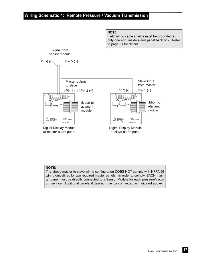
Wiring Schematic 4:  Remote Pressure / Vacuum Transmission


                                                                   NOTE:
                                                                   Field wiring cable shields must be grounded at
                                                                   only one end, inside alarm panel back box.  Refer
                                                                   to page 31 for details.

                                 Signal from
                               sensor module

                          Pin 6 (-)      Pin 5 (+)


                                         Master output                               Slave input
                                         to slave                                    from master
                                         Pin 4 (-) / Pin 3 (+)           Pin 2 (-)    Pin 1 (+)


                                                   ribbon to                               ribbon to
                                                   adjacent                                adjacent
                                                   module                                  module


                           Digital Display Module                   Digital Display Module
                           at master alarm panel                     at slave alarm panel


                             NOTE:
                             The above master to slave wiring configuration DOES NOT comply with NFPA 99
                             wiring guidelines for two required master panels.  In order to comply, EACH mas-
                             ter panel must be directly connected to a Sensor Module for each pressure/vacu-
                             um service.  Additional panels, if desired, may be connected as indicated above.


                                                                                                                 17
                                                                                            Part No. 6-847684-00 Rev. E00
   537   538   539   540   541   542   543   544   545   546   547