Page 273 - Womens Pavilion
P. 273

Oil-Less Claw Medical Vacuum


           2.0  Installation


           2.4  Locations Above Sea Level                      2.5  Electrical Requirements

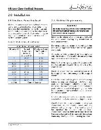
           All vacuum pumps above sea level have reduced                          WARNING:
           fl ow and should be de-rated.  After determining
           the correct fl ow needed for the medical vacuum        BE SURE THAT ALL POWER IS TURNED OFF
           system, multiply this number by the adjustment        PRIOR TO PERFORMING ANY WORK ON
           factor located in Table 2.1.  After determining the   THE ELECTRICAL PANEL!
           new fl ow required, use this number to size the
           medical vacuum system.                              Refer to the electrical diagram provided with
                                                               the unit before starting any installation or
           Table 2.1 Altitude Adjustment Factor                maintenance work.

                                                               Do not operate vacuum pump on a voltage other
                     Altitude Adjustment Factor
                                                               than the voltage specifi ed on the control panel
            Altitude (ft)    Normal        Multiplier Used     nameplate.
                            Barometric      for Required
                             Pressure           SCFM           All customer wiring should be in compliance
                           (inches HG)
                                                               with the National Electrical Code and any other
                 0            29.92             1.00           applicable state or local codes.
                500           29.39             1.02
                                                               Refer to the wiring diagram(s) that came with
               1000           28.86             1.04
                                                               the vacuum pump system for pertinent wiring
               1500           28.33             1.06           connections.
               2000           27.82             1.08
               2500           27.32              1.10          Electrical power for the medical system must
                                                               be supplied from the emergency life support
               3000           26.82              1.12
                                                               circuit.
               3500           26.33              1.14
               4000           25.84              1.16          Check the control voltage, phase, and amp ratings
               >4000              Contact Factory              before starting the electrical installation, and
                                                               make sure the voltage supplied by the hospital is
                                                               the same. The wire size should be able to handle
                                                               peak motor amp load of all operating units.  Refer
                                                               to the vacuum pump system full load amperes on
                                                               the wiring diagram.

                                                               Check all electrical connections within the vacuum
                                                               system that may have loosened during shipment.


                                                               Qualifi ed electricians only should make power
                                                               connections to the control panel and any
                                                               interconnecting wiring.  The control panel
                                                               has openings for electrical and alarm/data
                                                               connections.  Do not drill additional holes in
                                                               the control panel as this may void the system
                                                               warranty.  See Figure 2.1 for opening locations.


           4107 9000 95.04                                  2-2
   268   269   270   271   272   273   274   275   276   277   278