
Page 6 - Hensler-Zavation Normandy EPS - 2019
P. 6
Normandy VBR System Surgical Technique Guide ST-017, rev 1
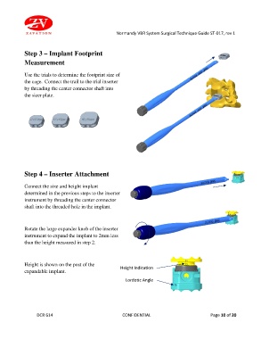
Step 3 – Implant Footprint
Measurement
Use the trials to determine the footprint size of
the cage. Connect the trail to the trial inserter
by threading the center connector shaft into
the sizer plate.
Step 4 – Inserter Attachment
Connect the size and height implant
determined in the previous steps to the inserter
instrument by threading the center connector
shaft into the threaded hole in the implant.
Rotate the large expander knob of the inserter
instrument to expand the implant to 2mm less
than the height measured in step 2.
Height is shown on the post of the
expandable implant. Height Indication
Lordotic Angle
DCR 614 CONFIDENTIAL Page 10 of 20