
Page 26 - ansys
P. 26
Extrude: Use the Extrude button to create an extruded feature. The active sketch is the default
input but can be changed by selecting the desired sketch, a plane from face (boundary used) or Named
Selection features of Point features in the Tree Outline. Geometric entities such as faces, edges, vertices
or point feature points can also be selected as input for the Extrusion feature.
You can select either a sketch or a plane or combination of number of named selection features, point
features and/or geometry entities as input geometry. If the input geometry is other than sketch or
plane, then a Direction Vector must be defined, and will be used for extruding all entities specified.
Extrude can use faces (its edges are actually used), edges, surface bodies (treated like faces), line
bodies (treated like edges) as input geometric entities as well as from named selections. Point feature
points and vertices can also be selected as input geometry.
If the input geometry contains closed sets of edges and/or faces, only the closed sets of edges and/or
faces will be used for extrusion. If there are no closed sets of edges and/or faces, then only open sets of
edges will be used for extrusion. Vertices and point feature points will be used when nothing else is
selected for extrusion.
The Details View is used to set the Extrude depth, direction vector, direction, direction type and
modeling operation (Add, Cut, Slice, Imprint, or Add Frozen). When point profiles are to be extruded
only the Add Material and Add Frozen options are available. Clicking Generate completes the feature
creation and updates the model.
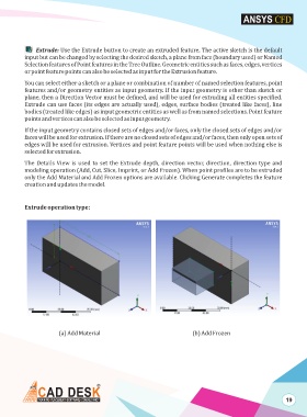
Extrude operation type:
(a) Add Material (b) Add Frozen
19