Page 1187 - Chief Architect Reference Manual
P. 1187
Chief Architect X10 Reference Manual


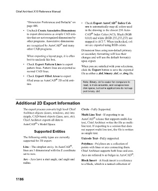
                           “Dimension Preferences and Defaults” on   • Check Export AutoCAD  Index Col-
                                                                                       ®
                           page 446.                              ors to automatically map all colors used
                        • Uncheck Create Associative Dimensions   in the drawing to the closest 256 Auto-
                                                                       ®
                           to export dimensions as simple CAD enti-  CAD  Index Color (ACI). Black (RGB
                           ties that are not recognized dimensions by   0,0,0) and white (RGB 255,255,255) are
                           other programs. Associative dimensions   mapped to ACI 7. When unchecked, col-
                                                  ®
                           are recognized by AutoCAD  and many    ors are exported using RGB colors.
                           other CAD programs.
                                                                Dimension lines using non-default primary
                                                                or secondary formatting will lose their
                           When exporting a layout page, it is often   changes and will use the default format(s)
                           best to uncheck this box.
                                                                upon export.
                        • Check Export Pattern Lines to export
                           pattern lines. Pattern lines are exported as   When you are satisfied with your selections,
                           normal CAD lines.                    click the Export button to save the exported
                                                                file as either a .dxf, binary .dxf, or .dwg file.
                        • Check Export Filled Areas to export
                                              ®
                           filled areas as AutoCAD  2D solid enti-  Note: Binary .dxf is easier for computers to
                           ties.                                 read, is more accurate, and occupies less
                                                                 disk space, but some applications do not sup-
                                                                 port binary .dxf.


                   Additional 2D Export Information

                        The export process converts high level Chief   Circle - Fully Supported.
                        Architect objects (doors, windows, etc) into   Multi Line Text - If exporting to an
                        simple, CAD-based objects (lines, arcs, etc).
                                                                        ®
                        Chief Architect exports all data to     AutoCAD  release that supports multi-line
                                ®
                        AutoCAD ’s Model Space.                 text, Chief Architect writes the file as multi-
                                                                line text. If exporting to a version that does
                                                                not support multi-line text, the file is written
                                Supported Entities
                                                                as simple text.
                        The following entity types are currently   Unicode Text - Fully supported.
                        supported for 2D export:
                                                                Polylines - Polylines are a collection of
                                                        ®
                        Line - The simplest entity. In AutoCAD ,   points with lines or arcs connecting them.
                        lines are 3 dimensional with the Z coordinate   Chief Architect supports both lines and arcs.
                        set to zero.                            Arcs are referred to as bulges in AutoCAD .
                                                                                                  ®
                        Arc - Arcs have a start angle, end angle and   Block Insert - A block insert is a reference
                        radius.                                 to a block, which is a named collection of


                   1186

