
Page 959 - Chief Architect Reference Manual
P. 959
Symbol Specification Dialog
1 Bounding Box Dimensions - Specify • Depth planes are oriented vertically and
the Width, Depth and Height of the run from one side of the symbol to the
selected symbol’s bounding box, measured other, or along the symbol’s Y axis.
from the symbol’s origin with 1/16" (1 mm) • Height planes are oriented horizontally,
accuracy. Not available when multiple or along the symbol’s Z axis.
symbols are selected.
When a symbol is first created, its bounding 3 Uniform Stretch Zones define an area
between two planes that stretches
box is the same size as the actual 3D object. uniformly when the object is resized, leaving
See “Bounding Boxes” on page 965. the area outside of the zone unaffected.
2 Stretch Planes define where a symbol
stretches when resized. If no stretch Note: Stretch Planes and Stretch Zones do
planes are used, the symbol resizes not affect a symbol’s 2D CAD block, which
uniformly. See “Stretch Planes and Zones” always resizes in a uniform manner. If you
on page 965. resize a symbol using custom Stretch Planes
and Zones, consider generating a new CAD
• Width planes are oriented vertically and Block. See “2D Block Panel” on page 955.
run from the back of the symbol to its
front, or along the symbol’s X axis.
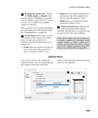
Cabinet Panel
The CABINET panel is only available for function of both the cabinet and its individual
Cabinet symbols as they are being imported. parts once it is imported.
The settings on this panel control the
959