
Page 155 - FreesStyler® Installation and Startup
P. 155
®
INSTALLATION AND STARTUP
Chapter 9 Optional “Add-On” Items
Water Softener
Kinetico Softener Installation CP 213
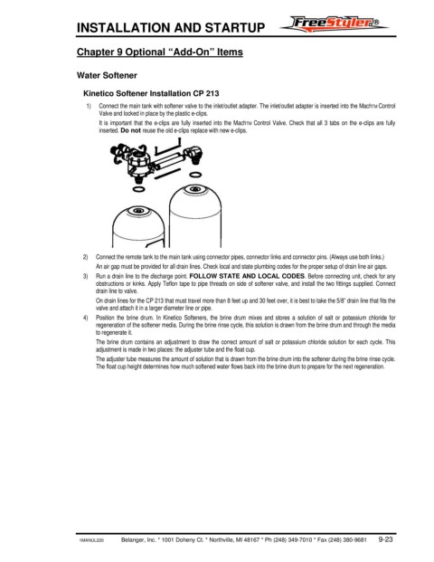
1) Connect the main tank with softener valve to the inlet/outlet adapter. The inlet/outlet adapter is inserted into the MachTM Control
Valve and locked in place by the plastic e-clips.
It is important that the e-clips are fully inserted into the MachTM Control Valve. Check that all 3 tabs on the e-clips are fully
inserted. Do not reuse the old e-clips replace with new e-clips.
2) Connect the remote tank to the main tank using connector pipes, connector links and connector pins. (Always use both links.)
An air gap must be provided for all drain lines. Check local and state plumbing codes for the proper setup of drain line air gaps.
3) Run a drain line to the discharge point. FOLLOW STATE AND LOCAL CODES. Before connecting unit, check for any
obstructions or kinks. Apply Teflon tape to pipe threads on side of softener valve, and install the two fittings supplied. Connect
drain line to valve.
On drain lines for the CP 213 that must travel more than 8 feet up and 30 feet over, it is best to take the 5/8” drain line that fits the
valve and attach it in a larger diameter line or pipe.
4) Position the brine drum. In Kinetico Softeners, the brine drum mixes and stores a solution of salt or potassium chloride for
regeneration of the softener media. During the brine rinse cycle, this solution is drawn from the brine drum and through the media
to regenerate it.
The brine drum contains an adjustment to draw the correct amount of salt or potassium chloride solution for each cycle. This
adjustment is made in two places: the adjuster tube and the float cup.
The adjuster tube measures the amount of solution that is drawn from the brine drum into the softener during the brine rinse cycle.
The float cup height determines how much softened water flows back into the brine drum to prepare for the next regeneration.
1MANUL220 Belanger, Inc. * 1001 Doheny Ct. * Northville, MI 48167 * Ph (248) 349-7010 * Fax (248) 380-9681 9-23