
Page 169 - Saber® Installation & Startup
P. 169
INSTALLATION & STARTUP
Chapter 12 Pneumatic
Pneumatic Manifold Connections
The pneumatic manifold will need to be mouted on a wall near the Machine Control Center (MCC).
Make all connections as shown on the following pages. Each component in this manual shows
adjoining connection details.
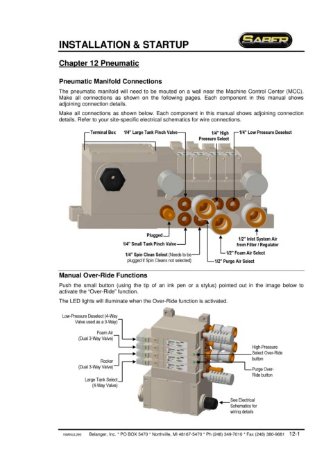
Make all connections as shown below. Each component in this manual shows adjoining connection
details. Refer to your site-specific electrical schematics for wire connections.
Terminal Box 1/4” Large Tank Pinch Valve 1/4” High 1/4” Low Pressure Deselect
Pressure Select
Plugged
1/2” Inlet System Air
1/4” Small Tank Pinch Valve from Filter / Regulator
1/4” Spin Clean Select (Needs to be 1/2” Foam Air Select
plugged if Spin Cleans not selected)
1/2” Purge Air Select
Manual Over-Ride Functions
Push the small button (using the tip of an ink pen or a stylus) pointed out in the image below to
activate the “Over-Ride” function.
The LED lights will illuminate when the Over-Ride function is activated.
Low-Pressure Deselect (4-Way
Valve used as a 3-Way)
Foam Air
(Dual 3-Way Valve)
High-Pressure
Select Over-Ride
button
Rocker
(Dual 3-Way Valve)
Purge Over-
Ride button
Large Tank Select
(4-Way Valve)
See Electrical
Schematics for
wiring details
1MANUL290 Belanger, Inc. * PO BOX 5470 * Northville, MI 48167-5470 * Ph (248) 349-7010 * Fax (248) 380-9681 12-1