
Page 34 - Saber® E-1063 Programming and Operation Manual
P. 34
1063 PROGRAMMING AND OPERATION
Chapter 3 Operator Interface/Programming
Setup
Setup / Misc / Sonar
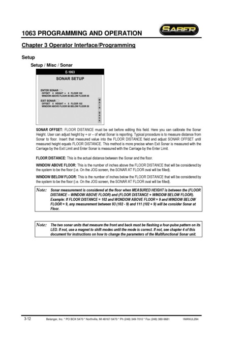
E-1063
SONAR OFFSET: FLOOR DISTANCE must be set before editing this field. Here you can calibrate the Sonar
Height. User can adjust height by + or – of what Sonar is reporting. Typical procedure is to measure distance from
Sonar to floor. Insert that measured value into the FLOOR DISTANCE field and adjust SONAR OFFSET until
measured height equals FLOOR DISTANCE. This method is more precise when Exit Sonar is measured with the
Carriage by the Exit Limit and Enter Sonar is measured with the Carriage by the Enter Limit.
FLOOR DISTANCE: This is the actual distance between the Sonar and the floor.
WINDOW ABOVE FLOOR: This is the number of inches above the FLOOR DISTANCE that will be considered by
the system to be the floor (i.e. On the JOG screen, the SONAR AT FLOOR oval will be filled).
WINDOW BELOW FLOOR: This is the number of inches below the FLOOR DISTANCE that will be considered by
the system to be the floor (i.e. On the JOG screen, the SONAR AT FLOOR oval will be filled).
Note: Sonar measurement is considered at the floor when MEASURED HEIGHT is between the (FLOOR
DISTANCE – WINDOW ABOVE FLOOR) and (FLOOR DISTANCE + WINDOW BELOW FLOOR).
Example: If FLOOR DISTANCE = 102 and WONDOW ABOVE FLOOR = 9 and WINDOW BELOW
FLOOR = 9, any measurement between 93 (102 - 9) and 111 (102 + 9) will be consider Sonar at
Floor.
Note: The two sonar units that measure the front and back must be flashing a four-pulse pattern on its
LED. If not, use a magnet to shift modes until the mode is correct. If not, see chapter 4 of this
document for instructions on how to change the parameters of the Multifunctional Sonar unit.
3-12 Belanger, Inc. * PO BOX 5470 * Northville, MI 48167-5470 * Ph (248) 349-7010 * Fax (248) 380-9681 1MANUL294