
Page 33 - Stanochny park
P. 33
PROFESSIONAL ADVICE PROFESSIONAL ADVICE
on the surface of the sleeve is proportional to the time t of the heat source with a power of q axis of the sleeve (see Fig. 2).
(W / m2) to this section, to this site. Traditionally, the workpiece
Depending on the ratio of the length and stroke of the hone, three heating schemes for is cooled by supplying coolant to overlapping
the workpiece are possible (see Fig. 1): the processing zone. To cool the matching
1) the processing areas in the extreme positions of the hone do not overlap, and a ‘‘gap‘‘is outer surface of the sleeve in the gap
obtained between the extreme positions of the distributed source (2), see Fig. 1a; cuff, deep grooves are performed
2) the processing areas in the extreme so that the coolant entering the
positions of the hone overlap (see Fig. Table 1. Processing modes and heat input into the cavity can also wash the outer wall
1b), the distributed source forms a workpiece. of the sleeve. Meanwhile, the cooling
‘‘overlap‘‘ (zone 3); rate can be increased by supplying
3) the source in extreme positions is Honing Type № Рок, Н рб, кPа W, m/с Р, кWe Q, kWe coolant through the cuff. To do
‘‘in contact‘‘, i.e. the overlap zone (3) Polishing 1 1536 400 0,67 1,0 0,62 this, it is enough to compress the
degenerates to a point. 2 1920 500 0,83 1,6 0,99 cuff with through holes in the wall
The graphs in fig. 1 reflect the 3 2304 600 1,00 2,3 1,48 using coolant. The simulation of the
speed of the extreme points of the heating and cooling process, the
distributed source in a given scale, Clean 4 2304 600 0,83 1,9 1,19 calculation of the temperature field
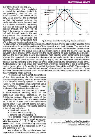
corresponding to the left (dashed line) 5 3072 800 1,00 3,1 1,97 of the liner were performed using the Fig. 2. Change in heat flux density along the axis of the sleeve
and right (solid line) end of the hone. 6 3840 1000 1,17 4,5 2,91 Flo application of the SolidWorks package. The FloWorks SolidWorks application uses the finite
In Fig. 1, the origin coincides with the volume method to solve the problems of fluid dynamics and heat transfer. The sleeve heat
middle section of the sleeve, and the Preliminary 7 3840 1000 1,00 3,8 2,46 transfer model takes into account the following physical effects: the movement of fluid in the
X axis, oriented along the axis of the Draft 8 5760 1500 1,17 6,7 4,37 channels formed by the sleeve wall and the rubber sleeve holding the sleeve (see Fig. 3),
sleeve, reflects the linear size reduced semi-clean 9 7680 2000 1,33 10,2 6,66 convective heat transfer of the sleeve with the liquid washing its outer surface, heat transfer
to scale, S is the hone course, A is the between the sleeve and the sleeve, and radiation heat transfer. When constructing the design
hone overrun, LГ and LХ are the length scheme, the opportunity to reduce the dimension of the model due to the symmetry of the
of the sleeve and the length of solution was used. The calculation results (see Fig. 3) are the streamlines and the velocity
the hone, respectively. fields of the fluid moving in the channels of the cooling jacket, the temperature fields of the
The duration of the heat fluid and solids. Figure 3a shows the velocity field of the fluid (3) moving in the channels of the
source on the site dF is determined cooling jacket, which is formed by the wall of the sleeve (1) and the cuff (2). The calculation
by the heating pattern of the was performed inside the computational area (4) with symmetric boundary conditions. Figure
workpiece and the X coordinate 3b shows the temperature field of the liner in the axial section of the computational domain for
of the site, because the average the overlapping heating circuit.
velocity and active length of the The nature of the thermal deformations
source LA, passing over the site of the liner obtained for the overlapping
dF, depend on the latter. scheme and processing mode No. 9 from table
From figure 1a we can Fig. 1. The location of the heat source. b 1 for different cooling options is shown in
conclude that for each scheme 1 - sleeve, 2 - hon. Figure 4. The calculation was performed using
the equality is true: a - the heat source in extreme positions does not form a zone of overlap, the SolidWorks Simulation application that
b - in extreme positions, the heat source forms an overlap zone 3.
implements finite element calculations.
Deformations are obtained as a result
of finite element modeling based on the
specialized Simulation application of the
SolidWorks package. The main results of the
calculations performed for processing modes
No. 2 and No. 9 from table 1 for a traditional
cooling circuit (TCC) and with cooling through a
or cuff are shown in table 2. The heating patterns
in table 2 are indicated:
● circuit with a gap - R,
● scheme with matching - C,
An exception is the overlap zone of the second circuit, in which the source heat is present ● scheme with overlapping - P.
all the time. The obtained values of temperatures
Calculating the source action time as the ratio of LA to the average hone speed V in an and geometry errors are in good agreement
arbitrary portion of the sleeve [x0; xφ]: with the results of [1, 2, 3, 4] and GOST R Fig. 3. The results of the simulation.
53809-2010. Thus, semi-finishing processing a - movement of the coolant in the cooling channels, b -
leads to heating of the workpiece to 87 ° C, temperature field of the sleeve.
and polishing to 37 ° C.
An analysis of the results shows that
it is possible to plot the distribution of the thermal power of a quasi-stationary source along the large values of the temperature of the sleeve
32 Stanochniy park Stanochniy park 33