
Page 24 - Aviation News - September 2017
P. 24
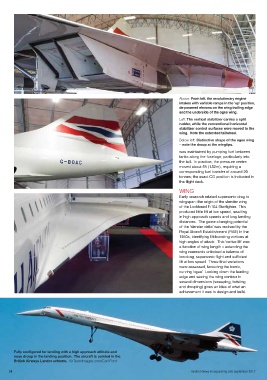
Above: From left, the revolutionary engine
                                                                                intakes with variable ramps in the ‘up’ position,
                                                                                de-powered elevons on the wing trailing edge
                                                                                and the underside of the ogee wing.
                                                                                Left: The vertical stabilizer carries a split
                                                                                rudder, while the conventional horizontal
                                                                                stabilizer control surfaces were moved to the
                                                                                wing.  Note the extended tailwheel.
                                                                                Below left: Distinctive shape of the ogee wing
                                                                                – note the droop at the wingtips.
                                                                                was maintained by pumping fuel between
                                                                                tanks along the fuselage, particularly into
                                                                                the tail.  In practice, the pressure centre
                                                                                moved about 5ft (1.52m), requiring a
                                                                                corresponding fuel transfer of around 20
                                                                                tonnes; the exact CG position is indicated in
                                                                                the flight deck.

                                                                                WING
                                                                                Early research related supersonic drag to
                                                                                wingspan: the origin of the slender wing
                                                                                of the Lockheed F-104 Starfighter.  This
                                                                                produced little lift at low speed, resulting
                                                                                in high approach speeds and long landing
                                                                                distances.  The game-changing potential
                                                                                of the ‘slender delta’ was realised by the
                                                                                Royal Aircraft Establishment (RAE) in the
                                                                                1950s, identifying lift-boosting vortices at
                                                                                high angles of attack.  This ‘vortex lift’ was
                                                                                a function of wing length – extending the
                                                                                wing rearwards unlocked a balance of
                                                                                low-drag, supersonic flight and sufficient
                                                                                lift at low speed.  Three final variations
                                                                                were assessed, favouring the iconic,
                                                                                curving ‘ogee’.  Looking down the leading
                                                                                edge and seeing the wing contour in
                                                                                several dimensions (sweeping, twisting
                                                                                and drooping) gives an idea of what an
                                                                                achievement it was to design and build.


       Fully configured for landing with a high approach attitude and
       nose droop in the landing position.  The aircraft is painted in the
       British Airways Landor scheme.  AirTeamImages.com/Carl Ford

     24                                                                              Aviation News incorporating Jets September 2017


  22-26_concordeDC.mfDC.mfDC.indd   24                                                                       04/08/2017   13:03