Page 393 - Foton Workshop Manual - Auman EST-M
P. 393

Diagnosis - Diagnosis-fault diagnosis of electronic and electrical parts   DI - 339

              Diagnosis procedure                                                                                 IN
              1. Check the circuit from door unlocked switch to combination instrument.

              a. Ignition switch: LOCK.                                                                           DI
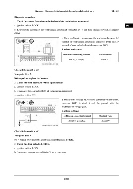
              b. Respectively disconnect the combination instrument connector B015 and door unlocked switch connector
              G004.                                                                                               EG

                                                        c.  Use  a  multimeter  to  measure  the  resistance  between  8#
                                                        terminal of combination instrument connector B015 and 1#   TR
                                                        terminal of door unlocked switch connector G004.

                                                        Standard resistance:
                                                                                                                  AX
                                                         Multimeter connecting terminal   Standard value

                                                               B015(8)-G004(1)             About 0Ω               FR


                                                                                                                  ST
              Check if the result is ok?

              Yes>go to Step 2.
                                                                                                                  BR
              NO>repair or replace the harness.

              2. Check the door unlocked switch signal circuit.
                                                                                                                  BW
              a. Ignition switch: LOCK.
              b. Disconnect the connector B015 of combination instrument.
                                                                                                                  EL
              c. Ignition switch: ON.

                                                        d. Measure the voltage between the combination instrument
                                                        connector  B015  terminal  8  and  the  ground  with  the
                                                        multimeter in voltage gear.

                                                        Standard voltage:

                                                          Multimeter connecting terminal   Standard value

                                                               B0015(8)-grounding           About 0V


              Check if the result is ok?

              Yes>go to Step 3.

              No > repair or replace the combination instrument module.

              3. Check the door unlocked switch.

              a. Ignition switch: LOCK.

              b. Disconnect the connector G004 of door is not closed .


                                                          DI-339
   388   389   390   391   392   393   394   395   396   397   398