
Page 2605 - Foton Workshop Manual - Sauvana
P. 2605
DIAGNOSIS-ENGINE CONTROL SYSTEM 62-553
P0325,P0327,P0328,P1386 - KNOCK SENSOR FAILURE
P0325-Open circuit of no.1knock sensor’ssignal ( below lower limit)
P0327-Open circuit of no.1knock sensor’s signal ( above upper limit)
P0328-High voltage of no.1knock sensor’s signal circuit
P1386-Improper control of knock signal
62
General
1. Knock sensor (KS) is used to detect the vibration of engine. Allowing theECUdelays
the ignitiontime of igniting control based on the received knock signal. KSgenerates
an alternating current (AC) signal. The amplitude and frequency of the knock signals
are based on the number of knocking experiences . The ECUcontains a non-
replaceable knock filter module called Signal/Noise Enlargement Filter (SNEF). The
filter module in the ECUdetermineswhether knocking has occurred by comparing
the knock signal levels on theKSwiring harness and on the channel of noise. The
noise channel allows theECUto reject anyunreal knocking signals by learning the
normal mechanical noise of the engine.
2. Changes of normal mechanical noise depend on the speed and load of the engine.
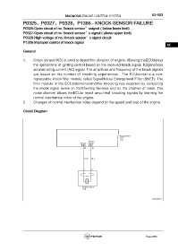
Circuit Diagram
Engine ECU
E01
C99
Sensor
Sensor+ signal
E01 E01
25 10
G-W W-L
1 2
Knock sensor
E19
fuwx62012
Page 2605