
Page 2611 - Foton Workshop Manual - Sauvana
P. 2611
DIAGNOSIS-ENGINE CONTROL SYSTEM 62-559
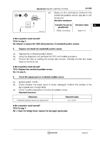
(d). Measure the resistance between the
crankshaft position sensor E22 pin 3 and
the ground.
Standard resistance:
Connect the pin by Standard value 62
pmultimeter
E22(3)- Grounding Approx 0Ω
Is the inspection result normal?
YES>To step 5.
No >Repair or replace the GND wiring harness of crankshaft position sensor.
5. Replace and check the crankshaft position sensor
(a). Replace the crankshaft position sensor.
(b). Using the diagnostic tool performs the DTC confirmation procedure.
(c). Perform the step of reading the sensor data stream. Indentify whether the check
result is normal or not.
Is the inspection result normal?
YES> Replace the crankshaft position sensor.
No >To step 6。
6. Check the signal panel of crankshaft position sensor
(a). Ignition switch: LOCK。
(b). Check whether the signal panel is looser damaged; whether the surface of the
signal panel has a foreign body.
(c). Check mounting clearance of crankshaft position sensor.
Standard clearance:
Clearance Standard value
Crankshaft position sensor and signal panel 0.3~1.5mm
Is the inspection result normal?
YES>To step 7.
No > Clean the foreign body; replace the damaged signal plate.
Page 2611