
Page 2614 - Foton Workshop Manual - Sauvana
P. 2614
62-562 DIAGNOSIS-ENGINE CONTROL SYSTEM
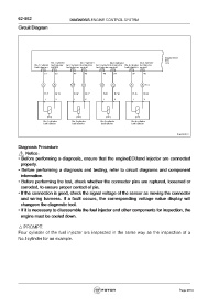
Circuit Diagram
Engine ECU
E01
No.1 cylinder No.2 cylinder No.3 cylinder No.4 cylinder C99
No.1 cylinder fuel injector No.2 cylinder fuel injector No.3 cylinderfuel injector No.4 cylinder fuel injector
fuel injector + control fuel injector+ control fuel injector+ control fuel injector+ control
E01 E01 E01 E01 E01 E01 E01 E01
31 33 47 49 46 34 32 48
1 5 2 6 3 7 4 8 E14
R-Y Br-R R-W Br-Y R-B Br-W R-G Br-B
1 2 1 2 1 2 1 2
No.1 cylinder No.2 cylinder No.3 cylinder No.4 cylinder
fuel injector fuel injector fuel injector fuel injector
fuwx62019
Diagnosis Procedure
Notice:
• Before performing a diagnosis, ensure that the engineECUand injector are connected
properly.
• Before performing a diagnosis and testing, refer to circuit diagrams and component
information.
• Before performing the test, check whether the connector pins are ruptured, loosened or
corroded, to ensure proper contact of pin.
• If the connection is good, check the signal voltage of the sensor as moving the connector
and wiring harness. If a fault occurs, the corresponding voltage value display will
changeon the diagnostic tool.
• If it is necessary to disassemble the fuel injector and other components for inspection, the
engine must be cooled down.
△ PROMPT:
Four cylinder of the fuel injector are inspected in the same way as the inspection of a
No.1cylinder for an example.
Page 2614