Page 179 - Foton Workshop Manual - Tunland (AT)
P. 179

DIAGNOSTICS - ANTI-LOCK BRAKING SYSTEM (ABS)                       04-33

                 C190004,C190104-ECU SUPPLY VOLTAGE FAULT

                 C190004-ECU THE SUPPLY VOLTAGE IS TOO HIGH
                 C190104-ECU THE SUPPLY VOLTAGE IS TOO LOW
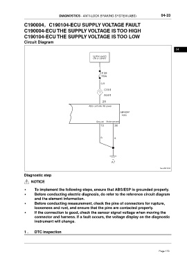
                 Circuit Diagram

                                                                                                                     04
                                                              Ignition switch
                                                              ON or START


                                                                    F26
                                                                   1 0A


                                                                   O-R
                                                                     C101
                                                                  1
                                                                     A301

                                                                    28
                                                           ABS controller IG power
                                                                                ABS/ESP
                                                                                 A006

                                                                Ground  Motor ground
                                                                   13       38


                                                                   B        B


                                                                          A7

                                                                                                          ftwxd041433

                 Diagnostic step

                      NOTICE

                 •      To implement the following steps, ensure that ABS/ESP is grounded properly.
                 •      Before conducting electric diagnosis, do refer to the reference circuit diagram
                        and the element information.

                 •      Before conducting measurement, check the pins of connectors for rupture,
                        looseness and rust, and ensure that the pins are contacted properly.
                 •      If the connection is good, check the sensor signal voltage when moving the
                        connector and harness. If a fault occurs, the voltage display on the diagnostic
                        instrument will change.


                 1 .    DTC inspection


                                                                                                         Page 179
   174   175   176   177   178   179   180   181   182   183   184