Page 201 - Foton Workshop Manual - Tunland (AT)
P. 201

DIAGNOSTICS - ANTI-LOCK BRAKING SYSTEM (ABS)                       04-55

                 U010004,U010008-ENGINE MANAGEMENT SYSTEM CAN FAULT

                 U010004-ENGINE MANAGEMENT SYSTEM CAN MESSAGE
                 TIMEOUT

                 U010008-ENGINE MANAGEMENT SYSTEM CAN DATA
                 INTERRUPTS / SIGNALS ARE INVALID                                                                    04
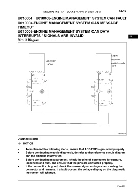
                 Circuit Diagram


                                                                                                    Engine
                                                                                                    electronic
                                          ABS/ESP
                                           A006                                                     control module
                                                                                                    E01


                           CAN-H CAN-L                                                 CAN-H CAN-L
                             26        14                                                15       16


                             R-W       L-Y                                               R-W      L-Y

                        A303                                                      E301

                            17       18                                                17        18
                        C102                                                      C501


                             R-W       L-Y                                               R-W      L-Y


                                                                                                          ftwxd041455

                 Diagnostic step
                      NOTICE


                 •      To implement the following steps, ensure that ABS/ESP is grounded properly.
                 •      Before conducting electric diagnosis, do refer to the reference circuit diagram
                        and the element information.
                 •      Before conducting measurement, check the pins of connectors for rupture,
                        looseness and rust, and ensure that the pins are contacted properly.
                 •      If the connection is good, check the sensor signal voltage when moving the
                        connector and harness. If a fault occurs, the voltage display on the diagnostic
                        instrument will change.


                                                                                                         Page 201
   196   197   198   199   200   201   202   203   204   205   206