
Page 199 - Foton Workshop Manual - Tunland (AT)
P. 199
DIAGNOSTICS - ANTI-LOCK BRAKING SYSTEM (ABS) 04-53
NOTICE
• To implement the following steps, ensure that ABS/ESP is grounded properly.
• Before conducting electric diagnosis, do refer to the reference circuit diagram
and the element information.
• Before conducting measurement, check the pins of connectors for rupture,
04
looseness and rust, and ensure that the pins are contacted properly.
• If the connection is good, check the sensor signal voltage when moving the
connector and harness. If a fault occurs, the voltage display on the diagnostic
instrument will change.
1 . DTC inspection
(a) Ignition switch: OFF.
(b) Connect the diagnostic apparatus.
(c) Use the diagnostic apparatus, read the fault code.
(d) Confirm whether there is a fault code related to CAN bus fault?
Is the inspection result normal?
YES>To step 2.
NO>Intermittent trouble exists.
2 . Check ABS/ESP_CAN communication circuit
(a) Ignition switch: OFF.
(b) Disconnect the battery negative cable.
(c) Disconnect ABS/ESP connector A006.
(d) Connect the battery negative cable.
(e) Ignition switch: ON.
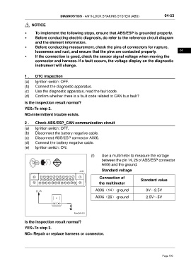
(f) Use a multimeter to measure the voltage
between the pin 14, 26 of ABS/ESP connector
A006 and the ground.
A006 Standard voltage
13 12 11 10 9 8 7 6 5 4 3 2 1 Connection of
24 23 22 21 20 19 18 17 16 15 14 Standard value
38 37 36 35 34 33 32 31 30 29 28 27 26 25 the multimeter
14 26 A006(14)-ground 0V~2.5V
A006(26)-ground 2.5V~5V
ftwxd041451
Is the inspection result normal?
YES>To step 3.
NO> Repair or replace harness or connector.
Page 199