
Page 2293 - Foton Workshop Manual - Tunland (AT)
P. 2293
WIRING - SYSTEM CIRCUIT DIAGRAM 71-91
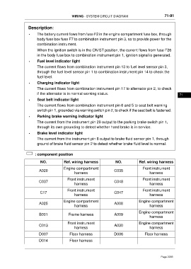
Description:
• The battery current flows from fuse F2 in the engine compartment fuse box, through
body fuse box fuse F7 to combination instrument pin 3, so to provide power for the
combination instrument.
When the ignition switch is in the ON/ST position, the current flows from fuse F26
in the body fuse box to combination instrument pin 1, ignition signal is generated.
• Fuel level indicator light
The current flows from combination instrument pin 13 to fuel level sensor pin 3,
through the fuel level sensor pin 1 to combination instrument pin 14 to check the
fuel level.
• Charging indicator light
The current flows from combination instrument pin 17 to alternator pin 2, to check
if the alternator is in normal working status. 71
• Seat belt indicator light
The current flows from combination instrument pin 6 and 5 to seat belt warning
switch pin 1, grounded via warning switch pin 2, to check if the seat belt is fastened.
• Parking brake warning indicator light
The current from the instrument pin 29 output to the parking brake switch pin 1,
through its own grounding to detect whether hand brake is in service.
• Brake level indicator light
The current from the instrument pin 8 output to brake fluid sensor pin 1, through
ground of brake fluid sensor pin 2 to detect whether brake fluid level is normal.
: component position
NO. Ref. wiring harness NO. Ref. wiring harness
Engine compartment Front instrument
A020 C035
harness harness
Front instrument Front instrument
C037 C048
harness harness
Front instrument Front instrument
C17 C047
harness harness
Engine compartment Engine compartment
A025 A008
harness harness
Engine compartment
B001 Frame harness A009
harness
Front instrument Engine compartment
C013 A030
harness harness
D007 Floor harness D006 Floor harness
D014 Floor harness
Page 2293