
Page 2290 - Foton Workshop Manual - Tunland (AT)
P. 2290
71-88 WIRING - SYSTEM CIRCUIT DIAGRAM
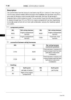
Description:
The current flows from the battery to low beam relay R2 pin 1 and pin 3, from relay pin
2 to the body control module; When turning on the headlamp, the low beam relay R2 is
grounded via the body control module. When electrified, the relay R2 generates a
magnetic field, and the contact is closed.The current then flows from the relay R2 contact
5, passes through fuse F21 and F22 in the engine compartment fuse box respectively,
to provide power to front left and front right combination lamp by the headlamp optical
axis switch.
: component position
NO. Ref. wiring harness NO. Ref. wiring harness
Engine compartment Engine compartment
A003 A020
harness harness
71
Engine compartment Front instrument
A011 C002
harness harness
: connectors between wiring harnesses
NO. NO. Ref. wiring harness
(connector position)
Front instrument harness and
engine compartment harness
C103 A304
(left side of instrument
crossbeam)
Front instrument harness and
engine compartment harness
C104 A305
(left side of instrument
crossbeam)
: Earthing
NO. Earth point NO. Earth point
A1 Left side of battery B6 Left A pillar
Right of the engine
A2
compartment
Page 2290