Page 2287 - Foton Workshop Manual - Tunland (AT)
P. 2287

WIRING - SYSTEM CIRCUIT DIAGRAM                             71-85


                   Description:

                   •     When the ignition is in the ON/ST position, the current flows from fuse F31 of the
                         indoor fuse box to pin 3 of reverse lamp relay R02, from reverse lamp relay pin 5
                         to reverse radar probe, Reverse signal communicate via LIN signal, then through
                         pin 1 of left reverse radar probe B006 to pin D31 of BCM connector C035. BCM
                         process the signal and send to combination instrument via CAN.

                   •     Reverse radar
                         The left reverse radar probe 2 pin provides the power signal and ground through
                         the 4 pin provides the sensor signal.
                         The right reverse radar probe 2 pin provides the power signal and ground through
                         the 1 pin to provides the sensor signal.


                                                                                                                     71
                   Service tips

                   •     R02 reverse lamp relay
                         3-5:When the transmission control mechanism is in reverse position, breakover.


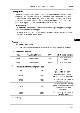
                        : component position

                           NO.            Ref. wiring harness              NO.            Ref. wiring harness
                                                                                             Front instrument
                          B006               Frame harness                C037
                                                                                                 harness
                          B009               Frame harness                E002               Engine harness


                        : connectors between wiring harnesses

                                                                                      Ref. wiring harness
                               NO.                             NO.
                                                                                      (connector position)
                                                                                    Floor harness and frame
                              B401                            D201
                                                                                  harness (under driver's seat)

                                                                                  Front instrument harness and
                              C701                            P201
                                                                                        gearbox harness
                                                                                  Front instrument harness and
                                                                                  engine compartment harness
                              C401                            D301
                                                                                     (left side of instrument
                                                                                           crossbeam)

                                                                                  Front instrument harness and
                              D201                            B401
                                                                                          frame harness

                        Earthing


                                                                                                        Page 2287
   2282   2283   2284   2285   2286   2287   2288   2289   2290   2291   2292