
Page 2282 - Foton Workshop Manual - Tunland (AT)
P. 2282
71-80 WIRING - SYSTEM CIRCUIT DIAGRAM
Description:
The battery current flows from the fuse F28 F19 in the engine compartment fuse box to
the horn relay R13 pin 1 and pin 3, through the horn relay R13 coil and pin 2 and output
to engine electrical control module pin D18. It then flows from the pin D5, through the
clock spring to the horn switch. When pressing, the horn switch is grounded and the
signal is transmitted from engine electrical control module pin D18.When electrified, the
horn relay R13 coil generates a magnetic field and the horn relay R13 closes.The current
then flows from the horn relay R13 contact point, through the pin 5 and output to the
tweeter pin 1 and woofer pin 1 respectively,then through the horn's inner coil and
grounded,the horn starts to work.
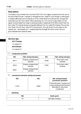
Service tips
71
• A017 Tweeter
1-2: about 2Ω
• A018 Woofer
1-2: about 2Ω
: component position
NO. Ref. wiring harness NO. Ref. wiring harness
Engine compartment Front instrument
A017 C009
harness harness
Engine compartment Front instrument
A018 C035
harness harness
Engine compartment
A020
harness
: connectors between wiring harnesses
NO. NO. Ref. wiring harness
(connector position)
Front instrument harness and
engine compartment harness
C103 A304
(left side of instrument
crossbeam)
: Earthing
NO. Earth point
A1 Left side of battery
Page 2282