Page 231 - Foton Workshop Manual - Tunland (AT)
        P. 231
     DIAGNOSTICS - ANTI-LOCK BRAKING SYSTEM (ABS)                       04-85
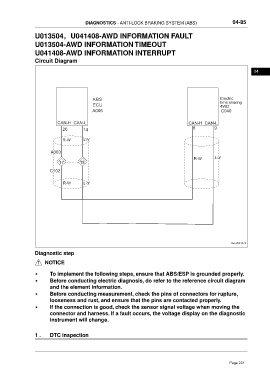
                 U013504,U041408-AWD INFORMATION FAULT
                 U013504-AWD INFORMATION TIMEOUT
                 U041408-AWD INFORMATION INTERRUPT
                 Circuit Diagram
                                                                                                                     04
                                           ABS                                                       Electric
                                                                                                     time sharing
                                           ECU                                                       4WD
                                           A006                                                      C040
                           CAN-H CAN-L                                                 CAN-H CAN-L
                             26        14                                                8        9
                             R-W       L-Y
                        A303
                                                                                         R-W       L-Y
                            17       18
                        C102
                              R-W      L-Y
                                                                                                          ftwxd041476
                 Diagnostic step
                      NOTICE
                 •      To implement the following steps, ensure that ABS/ESP is grounded properly.
                 •      Before conducting electric diagnosis, do refer to the reference circuit diagram
                        and the element information.
                 •      Before conducting measurement, check the pins of connectors for rupture,
                        looseness and rust, and ensure that the pins are contacted properly.
                 •      If the connection is good, check the sensor signal voltage when moving the
                        connector and harness. If a fault occurs, the voltage display on the diagnostic
                        instrument will change.
                 1 .    DTC inspection
                                                                                                         Page 231


