
Page 2320 - Foton Workshop Manual - Tunland (AT)
P. 2320
71-118 WIRING - SYSTEM CIRCUIT DIAGRAM
Description:
• The rear power windows are powered when the battery current flows from fuse
F14 in the fuse box of the engine compartment to pin B8 of BCM connector C033.
The front power windows are powered when the battery current flows from fuse
F13 in the fuse box of the engine compartment to pin B7 of BCM connector C033.
Energy saving power is supplied when the battery current flows from fuse F11 in
the fuse box of the engine compartment to pin C10 of BCM connector C034 via
the body fuse box F36.
The fog lamp is powered when the battery current flows from fuse F02 in the fuse
box of the engine compartment to pin B6 of BCM connector C033 via the body fuse
box F1.
The turn signals are powered when the battery current flows from fuse F02 in the
fuse box of the engine compartment to pin C6 of body control module connector
71
C034 via the body fuse box F5.
The position lamps are powered when the battery current flows from fuse F02 in
the fuse box of the engine compartment to pin C5 of body control module connector
C034 via the body fuse box F6.
• Ignition signal
When the ignition switch is ON/ST and the current passes through the body fuse
box F022 to pin E1 of BCM connector C036, the ACC is powered.When the ignition
switch is ON/ST and the current passes through the body fuse box F026 to pin E1
of BCM connector C036, the ignition switch is powered.
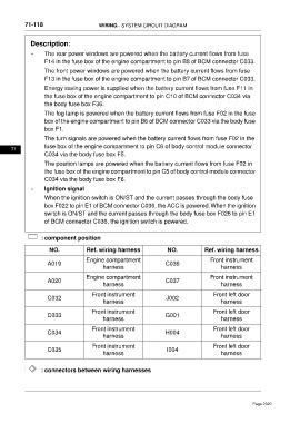
: component position
NO. Ref. wiring harness NO. Ref. wiring harness
Engine compartment Front instrument
A019 C036
harness harness
Engine compartment Front instrument
A020 C037
harness harness
Front instrument Front left door
C032 J002
harness harness
Front instrument Front left door
C033 G001
harness harness
Front instrument Front left door
C034 H004
harness harness
Front instrument Front left door
C035 I004
harness harness
: connectors between wiring harnesses
Page 2320