
Page 2324 - Foton Workshop Manual - Tunland (AT)
P. 2324
71-122 WIRING - SYSTEM CIRCUIT DIAGRAM
Description:
• Front roof lamp
The interior lamps are powered when the battery current flows from fuse box F2
of the engine compartment to pin C10 of body control module connector C034.
When the front roof lamp is switched on and the supply current outputs from pin
C12 of body control module connector C034 to pin 1 of the front lamp and is
grounded at pin 2, the front roof lamp light up.
• Rear roof lamp
The interior lamps are powered when the battery current flows from fuse box F2
of the engine compartment to pin C10 of body control module connector C034.
When the rear roof lamp is switched on and the supply current outputs from pin
C12 of body control module connector C034 and is grounded at pin 2 of the rear
lamp, the rear roof lamp light up.
71
• Door sill lamp
The interior lamps are powered when the battery current flows from fuse box F2
of the engine compartment to pin C10 of body control module connector C034.
When one of the doors is open, the door control switch is ON and the current
outputs from pin 2 of the door switch to provide door status information to body
control module. When the supply current outputs from pin C12 of body control
module connector C034 to pin 1 of the door switch via the filament and is grounded
at pin 1, the door sill lamp light up.
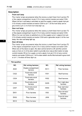
Part position
NO. Ref. wiring harness NO. Ref. wiring harness
Engine compartment
A020 D011 Floor harness
harness
Front instrument
C032 F001 Roof harness
harness
Front instrument
C034 F002 Roof harness
harness
Front instrument Front right door
C036 G005
harness harness
Front instrument Rear right door
C037 H003
harness harness
Rear left door
D001 Floor harness I003
harness
Front left door
D003 Floor harness J006
harness
D010 Floor harness
Page 2324