
Page 281 - Foton Workshop Manual - Tunland (AT)
P. 281
DIAGNOSTICS - ENGINE CONTROL SYSTEM 04-135
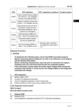
DTC DTC definition DTC inspection conditions Trouble location
Engine control module calibra-
P3697 tion memory - the intelligent
device or component fault
Engine protection torque de- 04
P3714
crease - the condition occurs
High pressure common rail fu-
el pressure reducing valve -
P3727
mechanical system is not re-
sponsive or misaligned
Anti lock brake (ABS) con-
P3488
troller - Abnormal update rate
Instrument control module -
P3731
Abnormal update rate
• During engine operation,
Anti lock braking (ABS) en-
P4215 the diagnosis continues to
abled - the condition exists
run
Diagnosis Procedure
NOTICE
• To implement the following steps, ensure that ECM is grounded properly.
• Before conducting electric diagnosis, do refer to the reference circuit diagram
and the element information.
• Before conducting measurement, check the pins of connectors for rupture,
looseness and rust, and ensure that the pins are contacted properly.
• If the connection is good, check the sensor signal voltage when moving the
connector and harness. If a fault occurs, the voltage display on the diagnostic
instrument will change.
1 . DTC inspection
(a) Ignition switch: OFF.
(b) Connect the diagnostic apparatus.
(c) Use the diagnostic apparatus, read the fault code.
(d) Confirm whether there is a fault code related to ECM?
Is the inspection result normal?
YES>To step 2.
NO>Intermittent trouble exists.
2 . Replace ECM
(a) Replace ECM.
(b) Use a diagnostic apparatus to perform DTC verification procedures.
Page 281