
Page 481 - Foton Workshop Manual - Tunland (AT)
P. 481
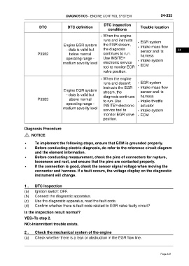
DIAGNOSTICS - ENGINE CONTROL SYSTEM                          04-335


                                                                    DTC inspection
                          DTC                DTC definition                                 Trouble location
                                                                       conditions
                                                                  • When the engine
                                                                    runs and instructs
                                                                                          • EGR system
                                          Engine EGR system         the EGR stream,       • Intake mass flow
                                            - data is valid but     the diagnosis           sensor and its           04
                         P3382                below normal          continues to run.       harness
                                            operating range -       Use INSITE™           • Intake system
                                          medium severity level     electronic service
                                                                    tool to monitor EGR   • ECM
                                                                    valve position.

                                                                  • When the engine
                                                                    runs and doesn't      • EGR system
                                                                    instructs the EGR     • Intake mass flow
                                          Engine EGR system         stream, the             sensor and its
                                            - data is valid but
                                                                    diagnosis continues     harness
                         P3383                above normal          to run. Use           • Intake throttle
                                            operating range -
                                                                    INSITE™ electronic      actuator
                                          medium severity level
                                                                    service tool to       • Intake system
                                                                    monitor EGR valve     • ECM
                                                                    position.


                 Diagnosis Procedure

                      NOTICE

                 •      To implement the following steps, ensure that ECM is grounded properly.
                 •      Before conducting electric diagnosis, do refer to the reference circuit diagram
                        and the element information.
                 •      Before conducting measurement, check the pins of connectors for rupture,
                        looseness and rust, and ensure that the pins are contacted properly.
                 •      If the connection is good, check the sensor signal voltage when moving the
                        connector and harness. If a fault occurs, the voltage display on the diagnostic
                        instrument will change.


                 1 .    DTC inspection

                 (a)    Ignition switch: OFF.
                 (b)    Connect the diagnostic apparatus.
                 (c)    Use the diagnostic apparatus, read the fault code.
                 (d)    Confirm whether there is fault code related to EGR valve faulty circuit?

                 Is the inspection result normal?

                 YES>To step 2.
                 NO>Intermittent trouble exists.

                 2 .    Check the mechanical system of the engine
                 (a)    Check whether there is a leak or obstruction in the EGR flow line.


                                                                                                         Page 481