
Page 2271 - Workshop Manual - Tunland (2017)
P. 2271
WIRING - SYSTEM CIRCUIT DIAGRAM 71-71
Description:
When the ignition switch is in the ON/ST position, the current flows from fuse F31 of the
instrument fuse box to reverse lamp switch pin 1 and reverse lamp switch pin 2, then to
rear left combination lamp pin 4 and rear right combination lamp pin 4, through the
reverse lamp filament,to rear left combination lamp pin 1 and rear right combination lamp
pin 1 and grounded. Then the reverse lamp starts to work.
Service tips
• E002 Reverse light switch
1-2: When the control mechanism of the transmission is engaged in the reverse
gear, the revese radar is on.
71
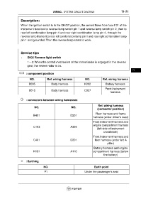
: component position
NO. Ref. wiring harness NO. Ref. wiring harness
B005 Body harness K002 Battery harness
Front instrument
B010 Body harness C037
harness
: connectors between wiring harnesses
Ref. wiring harness
NO. NO.
(connector position)
Floor harness and frame
B401 D201
harness (under driver's seat)
Front instrument harness and
engine compartment harness
C103 A304
(left side of instrument
crossbeam)
Front instrument harness and
C401 D301 floor harness (under left A
pillar)
Battery harness and engine
K101 A110 compartment harness (below
the battery)
: Earthing
NO. Earth point
F1 Under the passenger's seat