
Page 2276 - Workshop Manual - Tunland (2017)
P. 2276
71-76 WIRING - SYSTEM CIRCUIT DIAGRAM
Description:
• Battery power supply
The current flows from the instrument panel fuse box fuse F22 to the audio unit pin
4to make the audio unit work normally.
• Ignition switch power
The current flows from the fuse F2 in the engine compartment fuse box, through
the F3 in the body fuse box to the audio unit pin 7to make the audio unit work
normally.
Service tips
• c044 CD Controller
71
Pin 4earthing: When the ignition switch is in the ACC/ON position, the voltage is
about 12V.
Pin 7earthing: The voltage is about 12V.
Pin 8earthing: Always on.
• G004 Front right door speaker
1-2: about 4Ω
• H002 Rear right door speaker
1-2: about 4Ω
• I002 Rear left door speaker
1-2: about 4Ω
• J005 Front left door speaker
1-2: about 4Ω
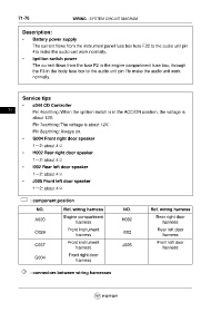
: component position
NO. Ref. wiring harness NO. Ref. wiring harness
Engine compartment Rear right door
A020 H002
harness harness
Front instrument Rear left door
C029 I002
harness harness
Front instrument Front left door
C037 J005
harness harness
Front right door
G004
harness
: connectors between wiring harnesses