
Page 2311 - Workshop Manual - Tunland (2017)
P. 2311
WIRING - SYSTEM CIRCUIT DIAGRAM 71-111
Description:
Battery current flows from fuse F2 in the engine compartment fuse box to fuse F4 in the
instrument panel fuse box, then to pin 1 of the tyre pressure monitor, supplying power
to the battery.
When the ignition switch is in position ON/ST, current flows from the body fuse box F30
to pin 5 of the tire pressure monitor, supplying power to the ignition switch.
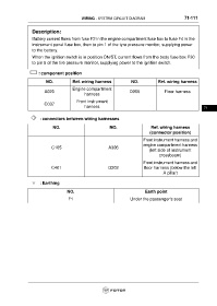
: component position
NO. Ref. wiring harness NO. Ref. wiring harness
Engine compartment
A020 D005 Floor harness
harness
Front instrument
C037
harness 71
: connectors between wiring harnesses
NO. NO. Ref. wiring harness
(connector position)
Front instrument harness and
engine compartment harness
C105 A306
(left side of instrument
crossbeam)
Front instrument harness and
C401 D302 floor harness (below the left
A pillar)
: Earthing
NO. Earth point
F1 Under the passenger's seat