
Page 385 - Workshop Manual - Tunland (2017)
P. 385
DIAGNOSTICS - POWER DOOR LOCK CONTROL SYSTEM 04-247
Diagnostic steps
• This diagnostic step follows right front door, and the diagnosis of other door is
the same as the right front door.
1 . Check motor control circuit, right front door lock
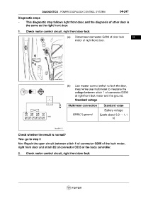
(a) Disconnect connector G006 of door lock 04
motor of right front door.
(b) Use master control switch to lock the door,
meanwhile use multimeter to measure the
voltage between stitch 1 of connector G006
of right front lock motor and the ground.
Standard voltage
Multimeter connection Standard value
Battery voltage
G006(1)-ground (Lasts about 0.3 ~ 1.1
s)
Check whether the result is normal?
Yes> go to step 3
No> Repair the open circuit between stitch 1 of connector G006 of the lock motor,
right front door and stitch B2 of connector C033 of the body controller.
2 . Check motor control circuit, right front door lock