
Page 826 - Workshop Manual - Tunland (2017)
P. 826
04-140 DIAGNOSTICS - ENGINE CONTROL SYSTEM
04 DTC inspection
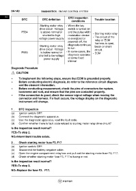
DTC DTC definition Trouble location
conditions
Starting motor relay • When the key
drive circuit -Voltage switch is turned on
P584 is above normal or and the pulse width
• Starting motor relay
shorted to high modulation device
voltage power supply is energized or • The circuit of the
relay or ECM
powered off, the
harness is open,
diagnosis continues
Starting motor relay break or short
to run
drive circuit -Voltage circuit .
P585 is below normal or • In some cases, the • ECM
diagnosis operates
shorted to low voltage
power supply at some fixed
interval
Diagnosis Procedure
CAUTION
• To implement the following steps, ensure that ECM is grounded properly.
• Before conducting electric diagnosis, do refer to the reference circuit diagram
and the element information.
• Before conducting measurement, check the pins of connectors for rupture,
looseness and rust, and ensure that the pins are contacted properly.
• If the connection is good, check the sensor signal voltage when moving the
connector and harness. If a fault occurs, the voltage display on the diagnostic
instrument will change.
1 . DTC inspection
(a) Ignition switch: OFF.
(b) Connect the diagnostic apparatus.
(c) Use the diagnostic apparatus, read the fault code.
(d) Confirm whether there is fault code related to starting motor relay drive circuit?
Is the inspection result normal?
YES>To step 2.
NO>Intermittent trouble exists.
2 . Check starting motor fuse F3, F17
(a) Ignition switch: OFF.
(b) Disconnect the battery negative cable.
(c) Open the engine compartment relay box and pull out the starting motor fuse F3, F17.
(d) Check whether starting motor fuse F3, F17 is fusing or not.
Is the inspection result normal?
YES>To step 3.
NO>Replace the fuse F3、F17.