
Page 780 - PPL-engelsk 2025
P. 780
Aircraft general knowledge
The direction indicator has therefore been developed.
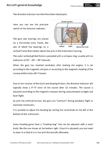
Here you can see the principle
sketch of the direction indicator.
The gyro axis bearings are placed
on a horizontal cross frame, the
axis of which has bearings on a
vertical frame that rotates about two pins in the instrument housing.
The outer vertical gimbal frame is provided with a compass ring, usually with an
o
o
o
indication of 30 – 60 – 90 intervals.
When the gyro has reached revolution after starting the engine, it is set
according to the magnetic compass or according to the magnetic heading of the
runway before take-off, if known.
Due to the rotation of the Earth and bearing friction, the direction indicator will
o
o
typically show a 4 –5 error of the course after 15 minutes. The course is
adjusted according to the magnetic compass during unaccelerated straight and
level flight.
As with the artificial horizon, the gyro can “overturn” during aerobatic flight or
excessive maneuvers.
It is possible to adjust the heading by turning the small knob on the left at the
bottom of the instrument.
Some heading gyros have a “heading bug” that can be adjusted with a small
knob, like the one shown at the bottom right. Once it is adjusted, you just need
to steer it so that it is in line with the aircraft silhouette.
Flyveteori PPL(A)(UL)/LAPL Henning Andersen, Midtjysk Flyveskole© 2025 780