
Page 144 - Zoo Animal Learning and Training
P. 144
Chapter 15: Atlantoaxial Subluxation 145
Reduction of the AAS can be quite challenging. The dorsally Means of Stabilization
recumbent surgical positioning coupled with retraction of the soft Transarticular pins are the simplest method of ventral fixation
tissues laterally by Gelpi self‐retaining retractors often provides described [27,28]. The pins are directed at an angle of 30° from the
partial reduction. A Hohmann retractor to lever the C2 body by midline (Figure 15.7). As intraoperative assessment of this angle
the ventral arch of C1 is commonly described. The author’s pre- can be difficult, a probe can be placed in the alar notch and this
ferred technique is to grasp the lateral body of C2 by a large point set as a target. The dorsoventral angle should engage the
Backhaus towel clamp or AO bone grasping forceps (Figure 15.6). wings of the atlas but this can be difficult to attain because of the
Ventrocaudal traction is provided until the dens can be visualized ventral soft tissues. A separate skin incision may be necessary for
against the ventral body of C1 and the articulation is automatically the drill to achieve the necessary angle. Newer 45‐degree chucks
correct. Alternate techniques recently described may provide a and drills make this angle more attainable.
more stable reduction until implants are placed [25,26]. In this Pin migration and loss of reduction are cited as the most com-
technique, a disc fenestration is made in the C2–C3 space. A Gelpi mon complication. Use of positive‐profile threaded pins or screws,
retractor is placed in the intercondyloid fissure of the occipital bone bent exit tips, and polymethylmethacrylate (PMMA) may decrease
and the C2–C3 fenestration to provide over‐distraction. Another this likelihood [29,30]. Other challenges with the technique include
technique for reduction is to use a C2 body screw as an anchor adequate bone purchase and potential distraction of the joint dur-
point. The body screw will later serve as part of a multi‐implant ing implant placement. Placement of screws in lag fashion may
construct [10]. therefore be preferable but add an extra step in the procedure
(Figures 15.8 and 15.9) [9].
Two techniques have been described that use transarticular fixa-
tion supplemented by nonarticular screws and PMMA stabiliza-
tion. Sanders et al. [31] placed transarticular screws followed by
screws in the transverse processes of C1, C2, and C3 (Figure 15.10).
These screws were “rebarred” with Steinman pins and cerclage wire
before completing the construct with PMMA. Platt et al. [10] used
a C2 body screw to facilitate joint reduction followed by tran-
sarticular Kirshner wires for temporary stabilization and incorpo-
ration of three other screws and PMMA. The techniques are likely
more rigid than transarticular stabilization alone but raise ques-
tions of over‐stabilization and of increasing the risk of domino
lesions at adjacent intervertebral disc spaces.
A 1.5‐mm five‐hole butterfly locking plate has been described
in three toy‐breed dogs; 6‐mm screws were used and laced at an
angle of 10° laterally from the perpendicular in the body of the
Figure 15.6 Backhaus towel clamps, fragment forceps, or AO bone grasping axis and variable angle in the wings of the atlas. The locking
forceps can be used to grasp the body of C2 for reduction of the atlantoaxial plate decreases the potential for screw pull‐out and failure.
joint. In this photo, a fragment forceps is attached to the body of C2 and is Titanium implants may prove advantageous in that they allow
used to reduce the subluxation. for later MRI [32].
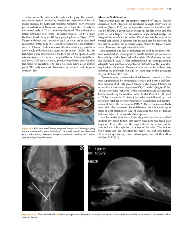
A B
Figure 15.7 (A) Ventrodorsal and (B) lateral postoperative radiographs showing position of transarticular pins used in an atlantoaxial subluxation reduc-
tion and fixation.