
Page 344 - Adams and Stashak's Lameness in Horses, 7th Edition
P. 344
310 Chapter 3
VetBooks.ir
B
A
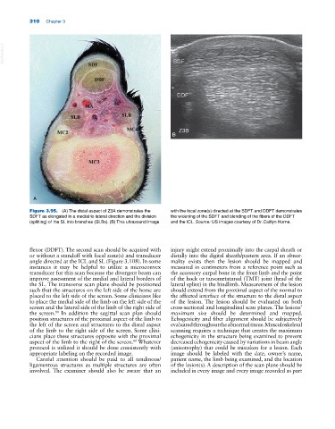
Figure 3.95. (A) The distal aspect of Z3A demonstrates the with the focal zone(s) directed at the SDFT and DDFT demonstrates
SDFT as elongated in a medial to lateral direction and the division the widening of the SDFT and blending of the fibers of the DDFT
(splitting) of the SL into branches (SLBs). (B) This ultrasound image and the ICL. Source: US images courtesy of Dr. Caitlyn Horne.
flexor (DDFT). The second scan should be acquired with injury might extend proximally into the carpal sheath or
or without a standoff with focal zone(s) and transducer distally into the digital sheath/pastern area. If an abnor
angle directed at the ICL and SL (Figure 3.108). In some mality exists then the lesion should be mapped and
instances it may be helpful to utilize a microconvex measured in centimeters from a reference point such as
transducer for this scan because the divergent beam can the accessory carpal bone in the front limb and the point
improve assessment of the medial and lateral borders of of the hock or tarsometatarsal (TMT) joint (head of the
the SL. The transverse scan plane should be positioned lateral splint) in the hindlimb. Measurement of the lesion
such that the structures on the left side of the horse are should extend from the proximal aspect of the normal to
placed to the left side of the screen. Some clinicians like the affected interface of the structure to the distal aspect
to place the medial side of the limb on the left side of the of the lesion. The lesion should be evaluated on both
screen and the lateral side of the limb of the right side of cross‐sectional and longitudinal scan planes. The lesions’
the screen. In addition the sagittal scan plan should maximum size should be determined and mapped.
80
position structures of the proximal aspect of the limb to Echogenicity and fiber alignment should be subjectively
the left of the screen and structures to the distal aspect evaluated throughout the abnormal tissue. Musculoskeletal
of the limb to the right side of the screen. Some clini scanning requires a technique that creates the maximum
cians place these structures opposite with the proximal echogenicity in the structure being examined to prevent
aspect of the limb to the right of the screen. Whatever decreased echogenicity caused by variations in beam angle
80
protocol is utilized it should be done consistently with (anisotrophy) that could be mistaken for a lesion. Each
appropriate labeling on the recorded image. image should be labeled with the date, owner’s name,
Careful attention should be paid to all tendinous/ patient name, the limb being examined, and the location
ligamentous structures as multiple structures are often of the lesion(s). A description of the scan plane should be
involved. The examiner should also be aware that an included in every image and every image recorded as part