
Page 423 - Adams and Stashak's Lameness in Horses, 7th Edition
P. 423
Diagnostic Imaging 389
VetBooks.ir
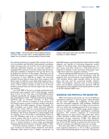
Figure 3.208. The G‐Scan Vet (Universal Medical Systems, imaging of the horse’s head, neck, and stifle more easily. Source:
®
Inc. Solon, OH) is an open, 0.25‐T low‐field magnet that can be Courtesy of Dr. Martin Waselau.
rotated from a horizontal to a vertical position to accommodate
the optimal position for imaging. This requires the horse high‐field images, several studies have shown that low‐field
to be recumbent and therefore under general anesthesia, magnets are capable of producing diagnostic quality
which increases the cost and the risk of the procedure. images of the distal limb, metacarpus/metatarsus, car
Although high‐field magnets are generally capable of pus, tarsus, and stifle. However, a high‐field system is
imaging limbs of horses from the carpus and tarsus dis required to identify certain structures and lesions, espe
tally, this capability is limited by how far the horse can cially those related to articular cartilage. 173,188,193
be pulled into the bore of the magnet. Therefore, not all Horses undergoing MRI must have all metal and fer
high‐field magnets are equal in this respect. Positioning rous material removed to avoid interference with the
in isocenter is more difficult in longer and narrower magnetic field and generation of susceptibility artifacts.
cylindrical bores than in some short bore magnets with This includes shoes, nails, metallic debris in the nail
flared ends. In addition, some high‐field magnets have a holes and sole, and the occasional metallic implant.
much tighter imaging window around the isocenter than Other ferromagnetic materials such as horse support
others, which makes it harder to pull areas of interest tables and anesthetic equipment may interfere with the
further proximal than the fetlock region into the imag homogeneity of the magnetic field and should be avoided
ing window. in the RF‐shielded MRI room.
Low‐field MRI of horses is currently performed with
permanent, open magnets with a field strength ranging
from 0.20 to 0.31 T. One open, low‐field MRI scanner SEQUENCES AND PROTOCOLS FOR EQUINE MRI
designed specifically for imaging distal limbs of stand
ing, sedated horses (EQ2 – Hallmarq Veterinary Imaging, MRI examinations rely on the use of several different
Guilford, UK) is mounted vertically at floor level acquisition sequences. Each sequence name describes
184
(Figure 3.207). However, imaging of areas proximal to the RF pulse applied, the weighting of that pulse,
the fetlock region is prone to motion artifact with these and the associated magnetic field gradients. Different
units. Other low‐field magnets (O‐Scan Equine®, Vet sequences used in conjunction to image a given anatom
MR Grande®, and G‐Scan Vet®, Universal Medical ical area define the imaging protocol. It is necessary to
Systems, Inc. Solon, OH) are oriented horizontally on a use several sequences in multiple image planes within a
pedestal and require horses to be placed under general protocol in order to identify pathological conditions
anesthesia. The O‐Scan Equine® is a small magnet with accurately. The common categories of conventional
an opening of 18 × 34 cm that is self‐shielded within its MRI sequences are spin echoes (SE), turbo spin echoes
own RF shielding cage with an internal thermostatic (TSEs), gradient recalled echoes (GRE) and short tau
control system and can be used in any nonspecialized inversion recovery sequences (STIR). The difference
room. The G‐Scan Vet® can be rotated from a horizon between these MR sequences lies in the method and tim
tal to a vertical position to more easily accommodate ing of how the RF signals are pulsed into the tissues and
imaging of the horse’s head, neck, and stifle (Figure 3.208). how the resonance is collected to generate an image.
Low‐field magnets produce a lower signal‐to‐noise Fast spin echo (FSE) or TSE sequences are used as a
ratio resulting in reduced image resolution and detail. more practical alternative to SE to reduce acquisition
Although many lesions have a higher conspicuity on times while maintaining signal‐to‐noise ratio. The purpose