
Page 3 - Cutting tool temperature prediction method using analytical model for end milling
P. 3
1790 W. Baohai et al.
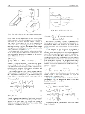
Fig. 2 Stress distribution on rake face.
Fig. 1 End milling diagram and approximation heating model.
Z t Z L x Z L y
a
Tðx; y; z; tÞ¼ Gðx; y; z; t; x p ; y ; 0; DÞ
p
k 0 0 0
cutting action, the conductor consists of insert and cutter has
p
p
Qðx p ; y ; sÞdy dx p ds ð4Þ
steady temperature. With the cutting action perform, it begins
to be heated by heat source over insert surface. According to The magnitude of heat flux is strongly affected by the fric-
heat transfer, the conductor like this can be assumed as a tion along the tool-chip interface. However, there are two dif-
semi-infinite body in analysis temperature change. Therefore, ferent friction states in this interface in the process of end
as an approximation, the insert is modeled as a semi-infinite milling, respectively called stick zone and slip zone, as shown
rectangular corner heated by a time-varying heat flux on the in Fig. 2.
tool-chip interface, as shown in Fig. 1. At the beginning of chip formation, the workpiece is
In this paper, with the heat radiation and temperature effect squeezed from the tool and in turn forms a chip. As a result,
on the thermal properties of the tool material neglected, the the shear stress e in the area that the chip closely contacts with
governing equation and boundary condition for the tempera- the tool tip is constant k chip . Moreover, there is very high nor-
ture T of the insert are set as mal stress r in this area. The chip is able to separate from the
workpiece on the condition that the shear stress is increasingly
(
2 1 @T
r T ¼ promoted. At this moment, the shear stress matches the normal
a @t ð1Þ
@T stress by the friction coefficient l. In this study, the heat flux Q
@t
k ¼ Qðx; y; tÞ z ¼ 0; 0 6 x 6 L x ; 0 6 y 6 L y
is considered to come from the uniform heat source and the
where a is the thermal diffusivity, t is the time, k the thermal liner heat source based on the following empirical equations:
conductivity, Q the heat flux, and L x and L y are the dimen-
Qðx; y; sÞ¼ q ðxÞqðsÞ ð5Þ
1
sions of the heat source. Except the interface between the tool
and chip, the rest surface of tool is regarded as insulated and 1 0 6 x 6 bL x
the initial temperature is set to be 0 °C. q ðxÞ¼ ð6Þ
1
The green function can be used to solve the above heat con- ðL x xÞ=½L x ð1 bÞ bL x 6 x 6 L x
5
duction equation. The green function G for the temperature where b is length ratio of stick zone over slip zone, q ðxÞ
1
of a semi-infinite corner excited by an instantaneous heat reflects the type of heat source distribution, and qðsÞ is the
source at time s at the surface point ðx ¼ x p ; y ¼ y ; z ¼ 0Þ is source heat flux varying with time.
p
Eqs. (5) and (6) then will be utilized to solve the tempera-
Gðx; y; z; x p ; y ; 0; DÞ ture equation. First, the inner double integral of the green
p
" !
2
2 z 2 ðx þ x p Þ function GR needs to be calculated:
¼ p ffiffiffi 3 exp 2 exp 2
ðD pÞ D D GRðx; y; z; L x ; L y ; DÞ
!# " !
2 2 Z L x Z L y
ðx x p Þ ðy þ y Þ
p
þ exp exp ¼ Gðx; y; z; t; x p ; y ; 0; DÞdx p dy p
p
D 2 D 2 0 0
" !
2 !# 2 z 2 Z L x ðx þ x p Þ 2
ðy y Þ ¼ exp exp
p
þ exp ð2Þ p ffiffiffi 3 D 2 D 2
D 2 ð D pÞ 0
!# " !
2 Z L y 2
ðx x p Þ ðy þ y Þ
p
þ exp exp
p ffiffiffiffiffiffiffiffiffiffiffiffiffiffiffiffi 2 dx p 2
D ¼ 2 aðt sÞ ð3Þ D 0 D
2 !#
where D is a parameter with units of length, and its physical ðy y Þ
p
þ exp dy ð7Þ
meaning is characteristic dimension for the penetration of tem- D 2 p
perature field at time t resulted from instantaneous heat source
at time s. According to Osakis’ theory, 18 the solution of the An error function erfðxÞ is introduced in the inner double
temperature in a semi-infinite corner is integral calculation: