
Page 6 - Cutting tool temperature prediction method using analytical model for end milling
P. 6
Cutting tool temperature prediction method using analytical model for end milling 1793
Table 5 Tool parameters.
Parameter Value
Tool type APMT 1135PDER DP5320
Tool rake angle 5°
Tool clearance angle 5°
Tool cutter diameter 16 mm
Fig. 5 Single wire thermocouple and tool.
Table 6 Critical cutting parameters.
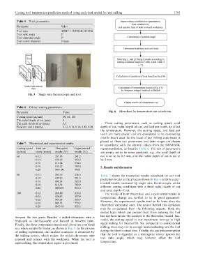
Parameter Value Fig. 6 Flowchart for temperature rise calculation.
Cutting speed (m/min) 60, 80, 100
The radial depth of cut (mm) 4
The axial depth of cut (mm) 0.5 Those cutting parameters, such as cutting speed, axial
Feed per tooth (mm/z) 0.12, 0.14, 0.16, 0.18, 0.20 depth of cut, radial depth of cut, and feed per tooth, do affect
the temperature. However, the cutting speed, and feed per
tooth are more crucial and are considered to be dominating
ones in insert wear. So the focus of our milling experiment is
placed on these two parameters and their ranges are chosen
Table 7 Theoretical and experimental results.
in accordance with the optimal values from the SANDVIK
Cutting speed Feed per Theoretical Experimental recommendation, as listed in Table 6. The rest of parameters
(m/min) tooth (mm/z) results (°C) results (°C) are simply set to be some constants, e.g., the axial depth of
60 0.12 297.93 241.2 cut is set to be 0.5 mm, and the radial depth of cut is set to
0.14 439.05 393.5 be 4 mm.
0.16 616.64 574.6
0.18 833.22 790.8 5. Results and discussion
0.20 1091.00 990.1
80 0.12 293.59 236.5 Table 7 shows the theoretical results calculated by our tool
0.14 432.15 391.5 prediction model as the process shown in Fig. 6 and the exper-
0.16 606.34 565.0 imental results measured by single wire thermocouple under
0.18 818.54 780.9
0.20 1070.90 953.4 different cutting conditions with a fixed radial depth of cut
and axial depth of cut.
100 0.12 289.80 230.2 The trends of both theoretical and experimental results in
0.14 426.13 387.9 temperature change are verified to be in good agreement.
0.16 597.34 555.7 However, the experimental results tend to be lower than the
0.18 805.73 773.2
0.20 1053.30 932.5 theoretical calculated ones. The reason behind this deviation
may be conjectured from the following aspects. First, the
coated layer which can prevent heat from entering the tool
has not been taken into account in the theoretical model. Sec-
between the two parts. Besides, a nickel–chromium wire is
ondly, the cutting speed in our experiment belongs to high
employed as thermocouple and located in between them.
speed milling for Inconel718. So, compared to conventional
Finally, the three components mentioned above are combined
milling, there may not be enough heat conducting into the tool
as a whole sample by binder, as shown in Fig. 5. In the process
during the short contact time. Thirdly, the analysis assumption
of milling experiment, the insulted conductor is destroyed by
that the tool is regarded as a rectangular corner ignores the
the milling action, which makes the nickel–chromium wire
tool rake angle, which may however affect the tool
exposed and contact with the workpiece. When the tool is
temperature.
approaching, the temperature signal is produced.