
Page 14 - TVH 2000 Anniversary Shipwreck Project
P. 14
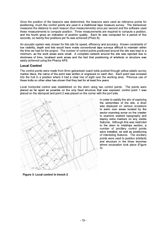
Once the position of the beacons was determined, the beacons were used as reference points for positioning, much like control points are used in a traditional tape measure survey. The transceiver measures the distance to each beacon (four measurements) once per second and the software used these measurements to compute position. Three measurements are required to compute a position, and the fourth gives an indication of position quality. Each fix was computed for a period of five seconds, so twenty-five positions per fix was achieved (Photo 8). An acoustic system was chosen for this site for speed, efficiency and accuracy. Known constraints of low visibility, depth and tide would have made conventional tape surveys difficult to maintain within the time we had for the project. The number of control points positioned around the site was kept to a minimum, as the work areas were small. A complete network around the site was rejected due to shortness of time, localised work areas and the fact that positioning of artefacts or structure was easily achieved using the Pharos APS. Local Control The control points were made from 8mm galvanised coach bolts pushed through yellow plastic survey marker discs, the name of the point was written or engraved on each disc. Each point was screwed into the hull in a position where it had a clear line of sight over the working area. Previous use of these bolts on other sites has shown that they last for at least five years. Local horizontal control was established on the stern using two control points. The points were placed as far apart as possible on the only fixed structure that was exposed, control point 1 was placed on the sternpost and point 2 was placed on the corner with the port side. In order to satisfy the aim of exploring the extremities of the site, a diver was deployed on various occasions to swim over areas located by the sector scanning sonar on the crawler to examine seabed topography and deploy extra markers on any visible features. Although this was restricted to the stern to midships section, a number of ancillary control points were installed, as well as positioning of interesting features. The ancillary points were used to position artefacts and structure in the three trenches where excavation took place (Figure 3). Figure 3: Local control in trench 2 - 12 -
