
Page 324 - Divyank Tyagi
P. 324
290 | ChAPter 8 AdvAnced Modeling And MAssing
Start by downloading and opening either c08-Massing-2-Start.rvt or c08-Massing-
2-Start-Metric.rvt from the book’s companion website, www.sybex.com/go/
MasteringRevit2015. Begin the exercise by following these steps:
1. Activate the Level 1 floor plan. From the Massing & Site tab in the ribbon, click In-Place
Mass and name the new family Mass 1.
2. From the Draw panel in the ribbon, choose the Rectangle tool. In the Options bar,
check the box to make a surface from closed loops. Sketch a rectangle that is
approximately 40’ × 90’ (12 m × 28 m). Specific dimensions are not important; it’s more
about the proportions.
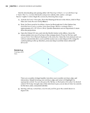
3. Open the Default 3D view, and click the Modify button in the ribbon. Hover the
mouse pointer over one of the lines in the rectangle sketch. Press the Tab key until
you see Form: Form Element displayed in the status bar. Select the form element and you
will see controls that allow you to pull the surface into a solid (Figure 8.35). Using the
control pointing in the up direction, press and drag it until the form is about 140’
(43 m) tall.
Figure 8.35
creating a solid
form
There are a number of shape handles that allow you to modify each face, edge, and
intersection. Simply hovering over each face, edge, and vertex will highlight the
appropriate control. You can also press the Tab key on the keyboard to select the desired
control. We’ll step through some of the selections to give you an idea of what the controls
for the faces, sides, and points look like.
4. Starting with any vertical face, select it and you’ll be given the control shown in
Figure 8.36.
c08.indd 290 05-05-2014 16:47:39