
Page 489 - Divyank Tyagi
P. 489
|
unDeRstanDing PHoto-RealistiC Visualization 455
The Output Settings options help you determine the level of resolution at which your image
can be saved when rendered. The screen resolution is simply the resolution of the view on your
monitor.
You should be much more interested in the Printer settings because of the likelihood that
you’ll need to print your views. Again, the resolution is important, because you’re printing for
something that will be viewed at some distance (arm’s length or a few feet away) with the naked
eye. Rendering beyond what can reasonably be seen will add a lot of time to your renderings.
While the default printer resolutions are shown in Figure 11.62, you can input other values by
typing them in the dialog box.
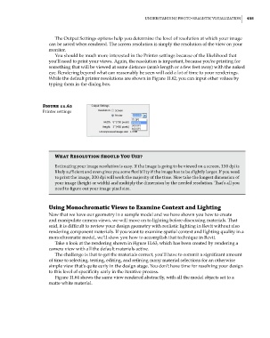
Figure 11.62
Printer settings
What Resolution Should You Use?
estimating your image resolution is easy. if the image is going to be viewed on a screen, 150 dpi is
likely sufficient and even gives you some flexibility if the image has to be slightly larger. if you need
to print the image, 300 dpi will work the majority of the time. now take the longest dimension of
your image (height or width) and multiply the dimension by the needed resolution. That’s all you
need to figure out your image pixel size.
Using Monochromatic Views to Examine Context and Lighting
Now that we have our geometry in a sample model and we have shown you how to create
and manipulate camera views, we will move on to lighting before discussing materials. That
said, it is difficult to review your design geometry with realistic lighting in Revit without also
rendering component materials. If you want to examine spatial context and lighting quality in a
monochromatic model, we’ll show you how to accomplish that technique in Revit.
Take a look at the rendering shown in Figure 11.63, which has been created by rendering a
camera view with all the default materials active.
The challenge is that to get the materials correct, you’ll have to commit a significant amount
of time to selecting, testing, editing, and refining many material selections for an otherwise
simple view that’s quite early in the design stage. You don’t have time for resolving your design
to this level of specificity early in the iterative process.
Figure 11.64 shows the same view rendered abstractly, with all the model objects set to a
matte white material.
c11.indd 455 5/3/2014 11:07:22 AM