
Page 580 - Divyank Tyagi
P. 580
546 | ChapTeR 13 Modeling Floors, Ceilings, and rooFs
wall position is modified, the roof will follow that change and adjust to the new wall position
without any intervention from you (Figure 13.10).
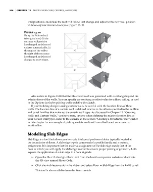
Figure 13.10
Using the pick method:
(a) original roof; (b) the
entrance wall position
has changed, and the roof
updates automatically; (c)
the angle of the wall to (a)
the right of the entrance
has changed, and the roof
changes to a new shape.
(b)
(c)
Also notice in Figure 13.10 that the illustrated roof was generated with overhangs beyond the
exterior faces of the walls. You can specify an overhang or offset value for a floor, ceiling, or roof
in the Options bar before picking walls to define the sketch.
If your building design is using curtain walls, be careful with the location lines of these
walls. The location line of a curtain wall is defined relative to the offsets specified in the mullion
and panel families that make up the curtain wall type. As discussed in Chapter 12, “Creating
Walls and Curtain Walls,” you have many options when defining the relative location line of
your curtain wall types. Refer to the exercise in the section “Creating a Structural Floor” earlier
in this chapter for an example of picking curtain walls with an offset based on a centered
location line.
Modeling Slab edges
Slab Edge is a tool that allows you to create thickened portions of slabs typically located at
the boundaries of floors. A slab edge type is composed of a profile family and a material
assignment. It is important that the material assignment of the slab edge match that of the
floor to which you will apply the slab edge in order to ensure proper joining of geometry. Let’s
explore the application of a slab edge to a floor at grade:
1. Open the file c13-Design-Floor.rvt from the book’s companion website and activate
the 3D view named Floors Only.
2. Click the Architecture tab in the ribbon and select Floor ➢ Slab Edge from the Build panel.
This tool is also available from the Structure tab.
c13.indd 546 05-05-2014 16:57:13